ALLPCB


Introduction
Fractures often result from severe trauma and high-energy injuries, and their incidence has been increasing. Internal fixation and surgical trauma are critical factors in fracture surgery. Besides preventing complications, the quality of reduction and internal fixation relative to surgical trauma is crucial for fracture treatment. Clinical evidence in orthopedics shows that two-dimensional planar images do not provide an intuitive, three-dimensional perception, which hinders communication between clinicians and patients and makes it harder for surgeons to explain operative plans. To make surgeries more precise and safer, this study applies 3D printing to produce physical bone models and bone repair guides, and develops an embedded FDM 3D printing image control system. The main development work was the framebuffer driver for the system's image control module. With this capability, patient CT data can be used to print a physical bone model, shape implantation guides accurately on the model, and then implant the shaped guide for bone repair.
1 Image transmission and display in the 3D printing image control system
Image data transmission in embedded systems requires a framebuffer controller under a Linux environment. Therefore, framebuffer-related knowledge is essential for this system. This research implemented the framebuffer driver to complete image transmission and display for the control system.
1.1 Framebuffer design for the embedded system
1.1.1 Overall control design of the FDM 3D printing image transmission framebuffer
The system uses an Atmega2560-16AU microcontroller (AVR core, 8-bit, 16 MHz, 256 KB Flash). The chip integrates many peripheral devices to support control functions. In the Linux source, the platform_device data structure in linux/platform_device.h is used to manage descriptions of these peripherals. All platform devices for the chip can be registered at system startup. The structure is as follows:
struct platform_device Atm2560_device_fb = {
    .name = "Atm2560-fb", // device name
    .id = -1, // id for multiple devices of the same type
    .num_resources = ARRAY_SIZE(Atm2560_fb_resource), // number of resources
    .resource = Atm2560_fb_resource, // pointer to array of resource structures
    .dev.dma_mask = &Atm2560_device_fb.dev.coherent_dma_mask,
    .dev.coherent_dma_mask = 0xffffffffUL,
};
1.1.2 Framebuffer driver architecture for the FDM 3D printing image transmission system
The framebuffer acts as an intermediary between user applications and hardware, similar to a graphics card. Operations on the framebuffer by applications are essentially operations on video memory. After the framebuffer is started, part of the device driver under linux/drivers/video/ must be implemented. The driver provides the interface between applications and the external device and depends on the chosen microcontroller to realize actual image display functions. The framebuffer device driver is covered by two kernel files:
- linux/include/linux/fb.h
- linux/drivers/video/fbmem.c
fb.h defines the key data structures used by framebuffer drivers. fbmem.c provides application-level interfaces to operate framebuffer devices so that basic operations are hardware independent, and also defines interfaces for lower-level hardware drivers. However, the actual hardware-specific operations are implemented by the platform-specific driver. In this project, Atm2560fb.c implements those operations and must provide interfaces specific to the LCD controller in use. The framebuffer driver structure is shown below.
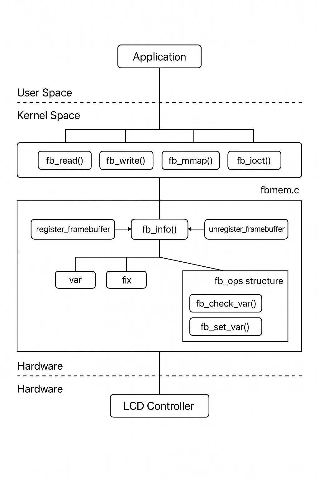
Figure 2 framebuffer driver structure
1.1.3 Framebuffer driver implementation
To enable correct image display, the framebuffer driver must be implemented. Drivers are hardware dependent and are organized in two layers: standard driver and non-standard (hardware-specific) driver.
The standard driver primarily provides operation interfaces for applications, with most operations implemented in fbmem.c file_operations. The lower-level driver implements the real device operations; in this system the framebuffer driver is located at drivers/video/Atm2560/Atm2560fb.c, and the complete driver information is stored in Atm2560fb_info_t.
Atm2560fb.c must include, among other items, initialization of fb_info members and binding the low-level driver to the platform device. Each platform_device is associated with a platform_driver to facilitate binding during driver loading.
2 System testing
Experiments used a TMKJ-ET series FDM 3D printer to validate the image control system workflow. Preoperative CT scans of orthopedic patients were imported into 3D modeling software to generate three-dimensional bone structures, as shown below.
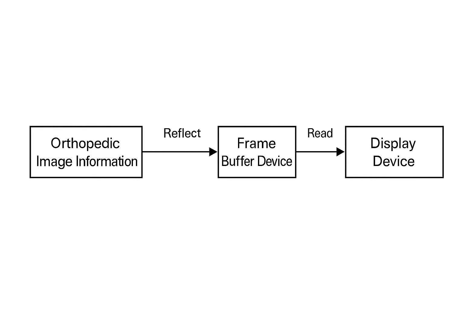
Figure 1 framebuffer working principle
Preoperative and postoperative CT data were used to reconstruct three-dimensional models. The repaired bone model was printed using the 3D printer, and the printed model was used to restore and shape the surgical guide. Finally, the accurately shaped guide was implanted into the patient to complete bone fixation and restoration.
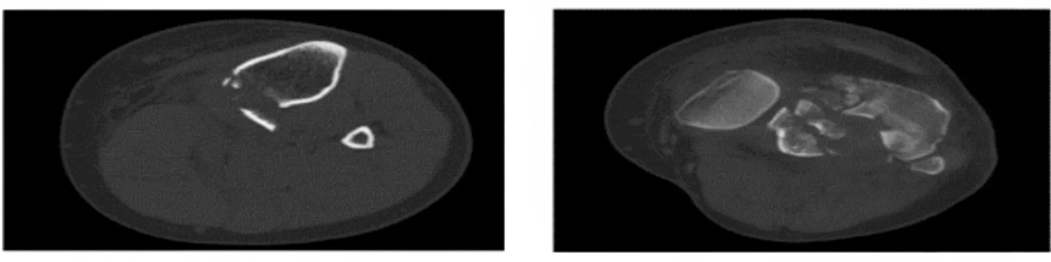
Figure 3 preoperative and postoperative CT images
Clinical validation showed the FDM 3D printing image control system operates with low latency, high interactivity, and stable performance. It can accurately print patient-specific orthopedic models, supporting precise surgical planning and guide fabrication.
3 Conclusion
This study used 3D printing to produce bone models and repair guides for surgical treatment. The framebuffer driver for the image control module was developed and tested. System tests confirm the image control system is simple to operate, efficient, and stable, and it enables precise 3D model printing for orthopedic surgery, supporting accurate surgical procedures.