 ALLPCB


Flexible printed circuit boards enable compact, lightweight designs that conform to three-dimensional spaces in modern electronic devices. Engineers in aerospace, medical, automotive, and consumer electronics sectors rely on them to reduce assembly steps and improve reliability under repeated flexing. Understanding cost drivers helps teams balance performance requirements with budget constraints during the design and procurement phases. Manufacturing facilities apply consistent processes to control expenses while meeting performance expectations outlined in industry standards.
What Are Flexible PCBs and Why Manufacturing Costs Matter
Flexible PCBs consist of thin, bendable substrates that support conductive traces and components. Unlike rigid boards, they incorporate materials that withstand dynamic or static bending without cracking or delaminating. This capability reduces the need for connectors and wiring harnesses in space-constrained applications.
Cost considerations influence decisions from initial layout through final production volumes. Procurement teams evaluate these factors to optimize total project expenses while maintaining quality levels required for end-use environments.
Primary Cost Drivers in Flex Circuit Manufacturing
Material selection represents one of the largest contributors to overall expense. Polyimide films serve as the primary substrate and coverlay due to their thermal stability and flexibility. Copper foil thickness, adhesive systems, and any stiffener additions further affect material budgets. Higher-performance grades or specialized constructions increase per-unit costs compared with standard configurations.
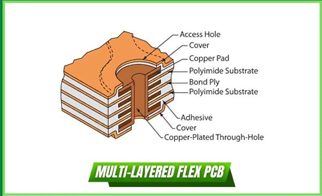
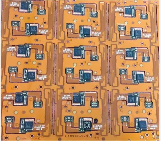
Layer count directly scales manufacturing complexity and material usage. Single- and double-sided designs require fewer lamination cycles and simpler processing than multilayer constructions. Each additional layer adds alignment precision requirements and potential yield impacts during fabrication. Panel utilization efficiency also plays a significant role, as designs that pack circuits densely on standard panel sizes minimize wasted substrate area.
Surface finish choices and stiffener integration introduce additional variables. Finishes such as immersion gold or silver provide solderability and oxidation resistance but vary in application cost. Stiffeners, typically FR-4 or polyimide, reinforce areas for component mounting and add both material and processing steps. Production volume influences economies of scale, with higher quantities generally lowering per-unit costs through optimized setup and material purchasing.
Manufacturing Process Influences on Cost
Fabrication steps for flexible circuits involve specialized handling to preserve material integrity. Etching, drilling or laser processing, and coverlay application each contribute to labor and equipment time. Lamination of multiple layers demands precise temperature and pressure control to avoid defects such as delamination or misalignment. Factories monitor these parameters closely to maintain acceptable yields.
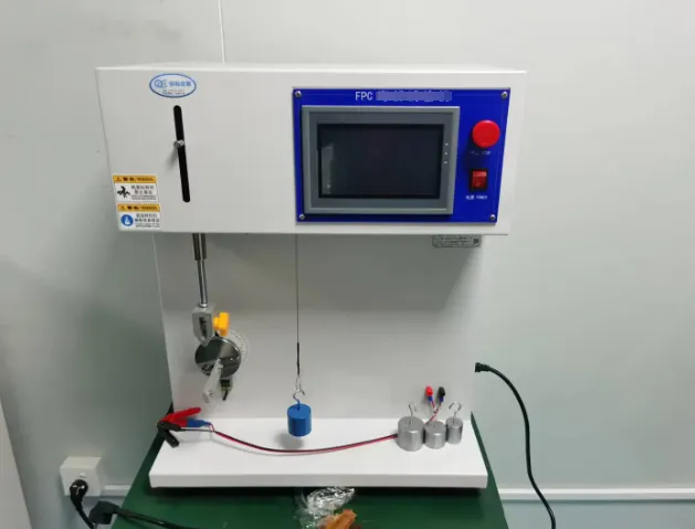
Quality control procedures add measurable expense but reduce downstream failures. Electrical testing, visual inspection, and mechanical verification ensure compliance with performance specifications. Standards such as IPC-6013 guide qualification and performance requirements for flexible printed boards, helping manufacturers establish consistent acceptance criteria. Design guidelines in IPC-2223 support decisions that affect manufacturability and long-term reliability.
Best Practices for Managing Flexible PCB Costs
Early collaboration between design and manufacturing teams identifies opportunities to simplify constructions without compromising function. Specifying minimum bend radii according to application needs avoids over-engineering. Selecting standard material thicknesses and finishes reduces lead times and procurement premiums. Optimizing board outlines for efficient panelization improves material utilization rates.
Volume planning and design for manufacturability reviews further control expenses. Engineers evaluate whether single-sided constructions suffice for low-flex applications or if multilayer approaches are necessary only where routing density demands them. Documented process controls aligned with IPC-6013 help maintain quality while minimizing scrap.
Conclusion
Material choices, layer count, panel efficiency, and process controls collectively determine flexible PCB costs. Applying standard-aligned practices throughout design and production supports predictable pricing and reliable performance. Teams that address these drivers early achieve better outcomes in both prototype and volume phases.
FAQs
Q1: What factors most influence flexible PCB cost?
A1: Material selection, layer count, and panel utilization represent the primary drivers of flexible PCB cost. Design decisions made early in the process affect material consumption and manufacturing complexity. Factories apply standard process controls to manage these variables consistently.
Q2: How does layer count affect flex circuit cost?
A2: Each additional layer increases material usage, lamination steps, and alignment requirements, raising overall flex circuit cost. Single- or double-sided constructions generally offer lower expense while meeting many application needs. IPC-2223 design guidelines help engineers evaluate appropriate layer counts.
Q3: Why is polyimide commonly used in flexible PCB manufacturing?
A3: Polyimide provides the thermal stability, flexibility, and dielectric properties required for reliable flex circuits across temperature ranges. Its consistent performance supports qualification under IPC-6013 specifications for flexible printed. Alternative materials may reduce cost in low-demand applications but often limit bend endurance.
Q4: How can engineers reduce flexible PCB manufacturing expenses?
A4: Simplifying layer counts, optimizing panel layouts, and selecting standard finishes and thicknesses help control expenses. Early design reviews focused on manufacturability and adherence to IPC-2223 recommendations improve yield and reduce iterations.
References
IPC-6013E — Qualification and Performance Specification for Flexible Printed Boards. IPC, 2023
IPC-2223 — Sectional Design Standard for Flexible/Rigid-Flexible Printed Boards. IPC, 2023





