ALLPCB


In the fast-evolving world of avionics, where precision and reliability are non-negotiable, choosing the right PCB material for high-frequency systems is critical. While FR-4 has long been the standard for many electronic applications, it often falls short in high-frequency avionics due to signal loss and poor performance at microwave frequencies. So, what are the best alternatives? Advanced materials like PTFE-based laminates and specialized hydrocarbon ceramics offer superior performance for high-frequency avionics PCB material needs, ensuring low loss and high signal integrity.
In this comprehensive guide, we’ll dive deep into why FR-4 isn’t always the best choice for avionics systems and explore advanced low loss PCB material options for avionics. We’ll cover materials like PTFE and specialized laminates, their benefits for microwave avionics PCB designs, and how they meet the demanding requirements of modern aerospace applications. Whether you’re an engineer designing cutting-edge avionics or a procurement specialist seeking reliable materials, this post will equip you with the knowledge to make informed decisions.
Why FR-4 Falls Short for High-Frequency Avionics Systems
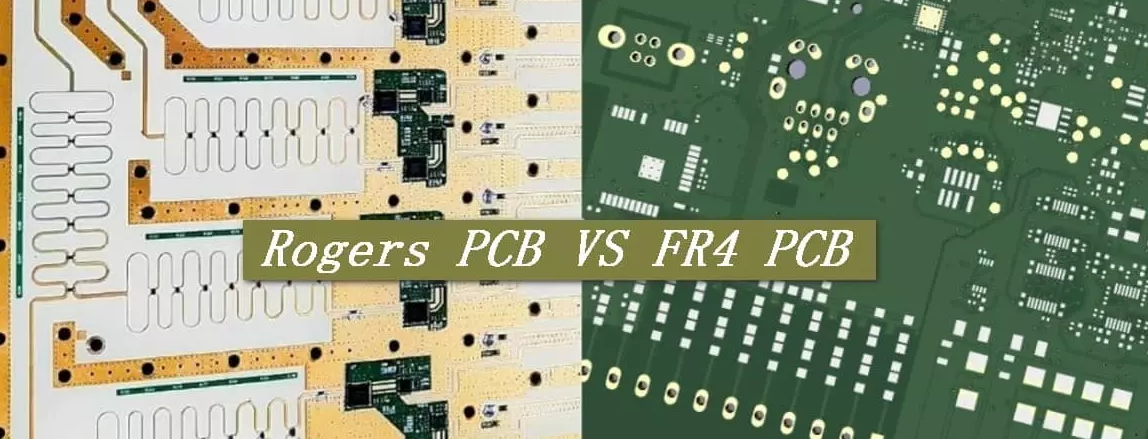
FR-4, a widely used PCB material made from woven fiberglass and epoxy resin, is cost-effective and versatile for many applications. However, when it comes to high-frequency avionics systems, its limitations become apparent. At frequencies above 1 GHz, FR-4 exhibits significant signal loss due to its relatively high dielectric constant (Dk) of around 4.5 and a dissipation factor (Df) of approximately 0.02. These properties lead to poor signal integrity, which is unacceptable in avionics where data transmission must be fast and accurate.
In avionics, systems like radar, satellite communication, and navigation often operate in the microwave frequency range (1 GHz to 30 GHz or higher). At these frequencies, FR-4 struggles to maintain signal strength, resulting in attenuation and potential data errors. Additionally, FR-4’s thermal stability is limited, which can be problematic in the extreme temperature variations experienced in aerospace environments, ranging from -55°C to over 125°C.
The Need for Advanced Materials in Avionics PCBs
High-frequency avionics systems demand materials that can handle rapid signal transmission with minimal loss, maintain stability across wide temperature ranges, and resist environmental stressors like humidity and vibration. Advanced materials specifically engineered for low loss PCB material avionics applications are designed to meet these challenges. They offer lower dielectric constants (typically between 2.2 and 3.5) and dissipation factors (as low as 0.0009), ensuring signals travel faster and with less attenuation.
These materials are critical for applications such as:
- Radar systems requiring precise microwave signal transmission.
- Satellite communication circuits operating at high frequencies.
- Navigation systems where signal clarity directly impacts accuracy.
By using advanced materials, engineers can design microwave avionics PCB layouts that minimize interference, reduce crosstalk, and improve overall system reliability. Let’s explore some of the top material options that go beyond FR-4.
PTFE-Based Materials: A Game-Changer for High-Frequency Avionics
Polytetrafluoroethylene (PTFE) is one of the most popular choices for high-frequency avionics PCB material. Known for its excellent electrical properties, PTFE offers a low dielectric constant of around 2.1 to 2.5 and an incredibly low dissipation factor of 0.0002 to 0.0004. This makes PTFE PCB avionics designs ideal for minimizing signal loss, even at frequencies exceeding 10 GHz.
PTFE materials are often reinforced with woven glass or ceramic fillers to enhance mechanical strength while maintaining their superior electrical performance. Their thermal stability is another key advantage, with operating temperatures ranging from -200°C to 260°C, far exceeding the capabilities of FR-4. This durability ensures reliability in the harsh conditions of avionics environments.
Additionally, PTFE’s resistance to moisture and chemicals makes it suitable for long-term use in aerospace applications where exposure to humidity or contaminants is a concern. However, PTFE can be more challenging to process during PCB fabrication due to its soft nature, often requiring specialized techniques to achieve precise drilling and plating.
Specialized Hydrocarbon Ceramics: Precision for Microwave Avionics PCB Designs
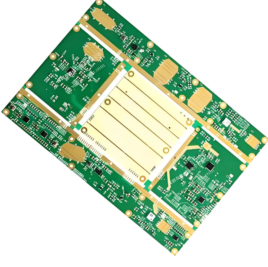
Another leading option for high-frequency avionics systems is a family of materials made from hydrocarbon ceramics with woven glass reinforcement. These materials are engineered to balance electrical performance with manufacturability, offering a dielectric constant of approximately 3.0 to 3.5 and a dissipation factor as low as 0.003. This makes them a top choice for Rogers PCB avionics applications operating in the microwave range.
These laminates excel in maintaining signal integrity at frequencies up to 20 GHz and beyond, making them perfect for radar and communication systems in aircraft. Their thermal conductivity is also higher than PTFE in some formulations, aiding in heat dissipation—a critical factor in densely packed avionics electronics. Moreover, they are often more compatible with standard PCB fabrication processes compared to pure PTFE, reducing production costs without sacrificing performance.
One notable advantage is their ability to support controlled impedance designs, which are essential for high-speed digital and RF signals in avionics. With impedance values tightly controlled to within ±10% of the target (e.g., 50 ohms for RF lines), these materials ensure consistent performance across the board.
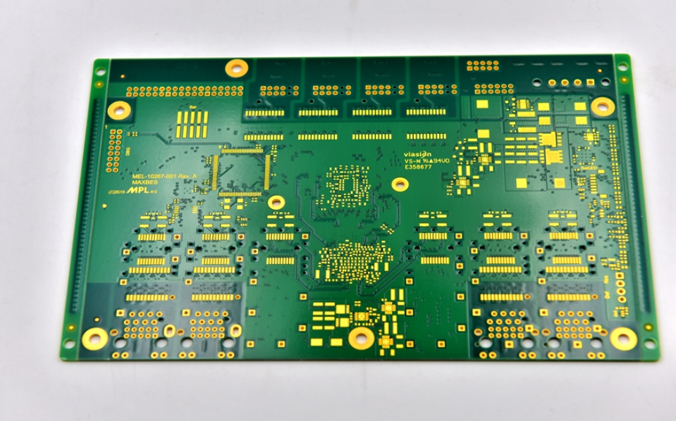
Key Benefits of Low Loss PCB Materials in Avionics
Switching to advanced low loss PCB material avionics options brings several tangible benefits that directly impact system performance and reliability. Here are the primary advantages:
- Improved Signal Integrity: With dissipation factors as low as 0.0009, these materials minimize signal attenuation, ensuring clear data transmission even at microwave frequencies.
- Thermal Stability: Advanced materials can withstand temperature swings from -55°C to 150°C or higher, maintaining performance in the extreme conditions of flight.
- Reduced Crosstalk: Lower dielectric constants reduce interference between adjacent traces, critical for densely packed avionics boards.
- Durability: Resistance to moisture, chemicals, and mechanical stress ensures long-term reliability in harsh environments.
- High-Speed Performance: Support for signal speeds exceeding 10 Gbps, meeting the demands of modern avionics communication systems.
These benefits translate into safer, more efficient aircraft systems, where every signal matters. Whether it’s ensuring accurate radar readings or maintaining uninterrupted satellite links, low loss materials are a cornerstone of high-frequency avionics design.
Comparing Advanced Materials: PTFE vs. Hydrocarbon Ceramics for Avionics
Choosing between PTFE PCB avionics materials and hydrocarbon ceramic laminates depends on the specific requirements of your project. Here’s a detailed comparison to guide your decision:
| Property | PTFE-Based Materials | Hydrocarbon Ceramics |
|---|---|---|
| Dielectric Constant (Dk) | 2.1 - 2.5 | 3.0 - 3.5 |
| Dissipation Factor (Df) | 0.0002 - 0.0004 | 0.003 - 0.004 |
| Frequency Range | Up to 30 GHz+ | Up to 20 GHz+ |
| Thermal Stability | -200°C to 260°C | -55°C to 150°C |
| Ease of Fabrication | More challenging | Easier, closer to standard processes |
| Cost | Higher | Moderate |
PTFE is the go-to choice for the highest frequency applications and extreme thermal conditions, while hydrocarbon ceramics offer a more cost-effective solution for slightly lower frequencies with easier manufacturing. Both are excellent low loss PCB material avionics options compared to FR-4.
Design Considerations for High-Frequency Avionics PCBs
When working with advanced materials for microwave avionics PCB designs, engineers must consider several factors to optimize performance:
- Impedance Control: Ensure trace widths and spacing are calculated for target impedance (e.g., 50 ohms for RF signals) to prevent signal reflection. Advanced materials support tighter tolerances, often within ±5% of the desired value.
- Layer Stackup: Design multilayer boards with proper grounding and power planes to minimize noise and maintain signal integrity.
- Thermal Management: Use materials with good thermal conductivity or integrate heat sinks to manage heat in high-power avionics systems.
- Environmental Factors: Select materials with low moisture absorption (less than 0.1%) to prevent performance degradation in humid conditions.
By addressing these considerations, you can fully leverage the advantages of high-frequency avionics PCB materials, ensuring robust and reliable performance.
Applications of Advanced Materials in Avionics Systems
Advanced materials are transforming avionics by enabling cutting-edge technologies. Here are some key areas where high-frequency avionics PCB materials shine:
- Radar Systems: Low loss materials ensure precise signal transmission for accurate detection and tracking, even at frequencies above 10 GHz.
- Satellite Communication: PTFE and hydrocarbon ceramics support high-speed data links with minimal signal degradation over long distances.
- Flight Control Systems: High signal integrity prevents errors in critical navigation and autopilot functions.
- Electronic Warfare: Advanced materials enable rapid signal processing for jamming and countermeasures in military avionics.
These applications highlight the indispensable role of low loss PCB material avionics solutions in modern aerospace technology.
Conclusion: Elevating Avionics with Advanced PCB Materials
As avionics systems continue to push the boundaries of speed and reliability, moving beyond FR-4 to advanced high-frequency avionics PCB materials is no longer optional—it’s essential. Options like PTFE and hydrocarbon ceramic laminates provide the low loss, thermal stability, and signal integrity needed for microwave avionics PCB designs. By understanding the unique properties of these materials, engineers can design systems that meet the rigorous demands of aerospace applications, from radar to satellite communication.
At ALLPCB, we’re committed to supporting your avionics projects with high-quality materials and manufacturing expertise. Whether you’re exploring PTFE PCB avionics solutions or specialized laminates for Rogers PCB avionics designs, our team is ready to help you achieve optimal performance. Embrace the future of avionics with advanced materials and unlock new possibilities for your designs.