ALLPCB


Overview
Abnormal high or low blood glucose levels can pose serious health risks, so monitoring glucose is essential. About 150 million people worldwide have diabetes, creating substantial demand for portable blood glucose meters.
Continuous Glucose Monitor Architecture
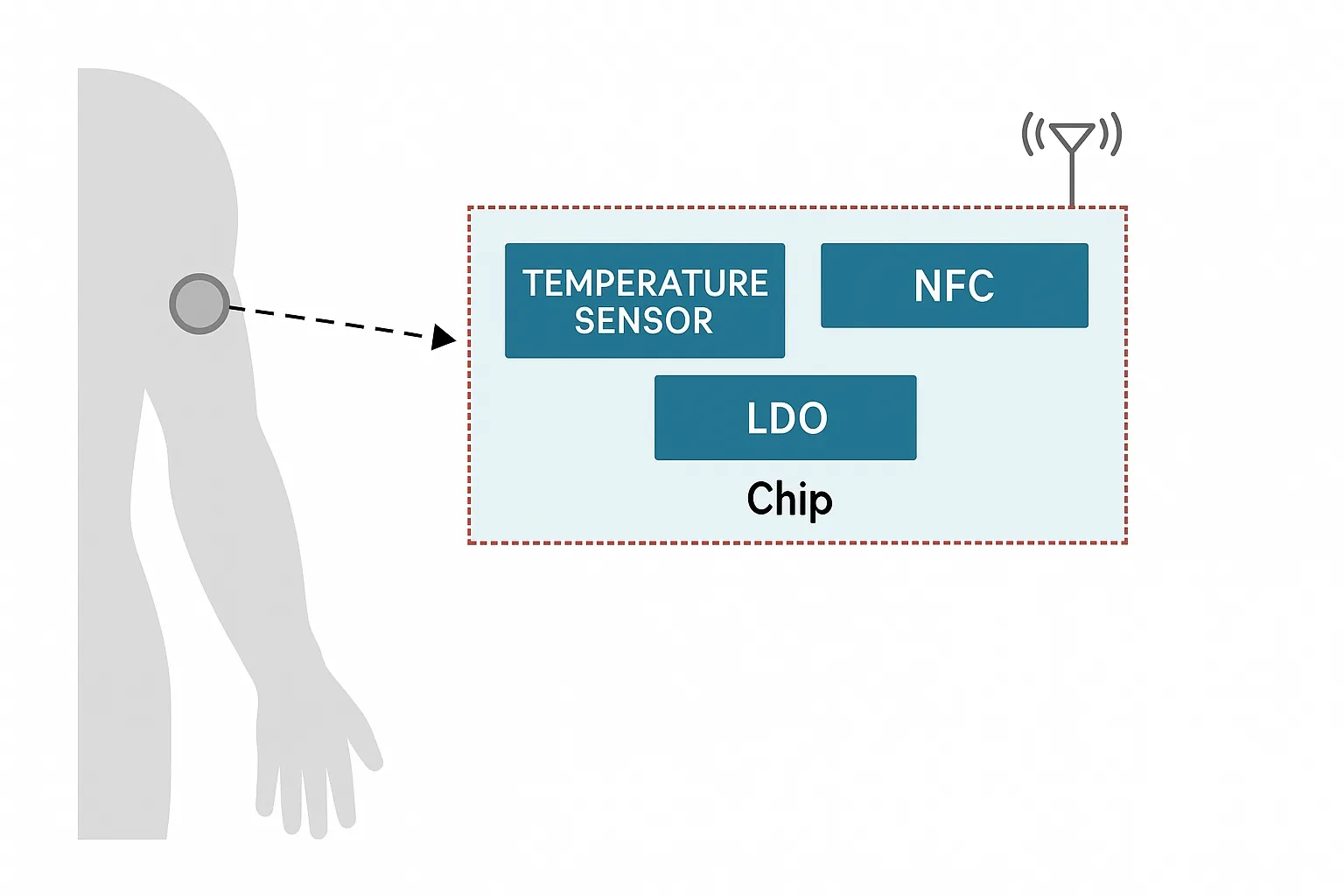
A continuous glucose monitor (CGM) helps users check glucose readings in real time and can monitor glucose over extended periods. A CGM typically comprises a sensor unit and an aggregator unit.
The sensor unit uses a coin cell or button cell and remains attached to the body for a limited period (for example, 8 to 10 days). The aggregator is a battery-powered handheld device that reads glucose data via wireless RF technologies such as near-field communication. The aggregator's battery management subsystem includes a battery charger, a fuel gauge, and protection circuitry. A 3.7 V single-cell lithium-ion battery commonly powers the aggregator and is charged through a power adapter using USB or DC input.
Role of the Fuel Gauge
A battery fuel gauge predicts and estimates remaining capacity, state of charge, time to empty, and battery health under varying load conditions, addressing key battery management challenges. Using a smart fuel gauge can extend runtime and battery cycle life.
Texas Instruments (TI) implements an Impedance Track measurement algorithm that achieves capacity estimation accuracy greater than 99%, providing accurate analog measurement and battery-characterization capabilities.
System-Side and Pack-Side Fuel Gauge Options
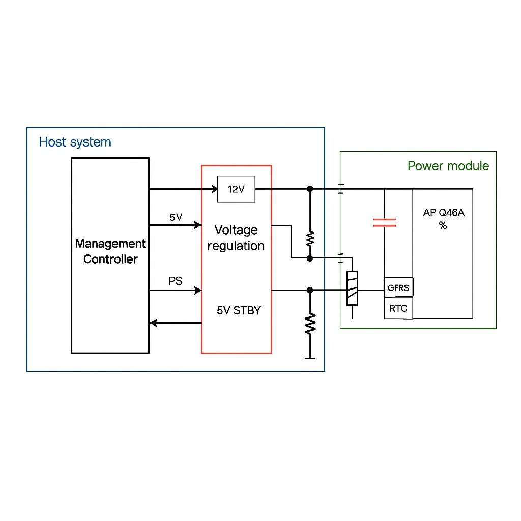
Fuel gauge solutions for a single cell are available that are compact, cost-effective, and extremely low power. The fuel gauge can be placed on the battery pack or on the system PCB, with the latter being more common in portable medical devices.
Typical system-side and pack-side fuel gauge configurations are shown below. A system PCB fuel gauge such as the BQ27426 requires minimal user configuration and consumes low operating current. For higher integration, some fuel gauges include an integrated sense resistor, for example BQ27421-G1.
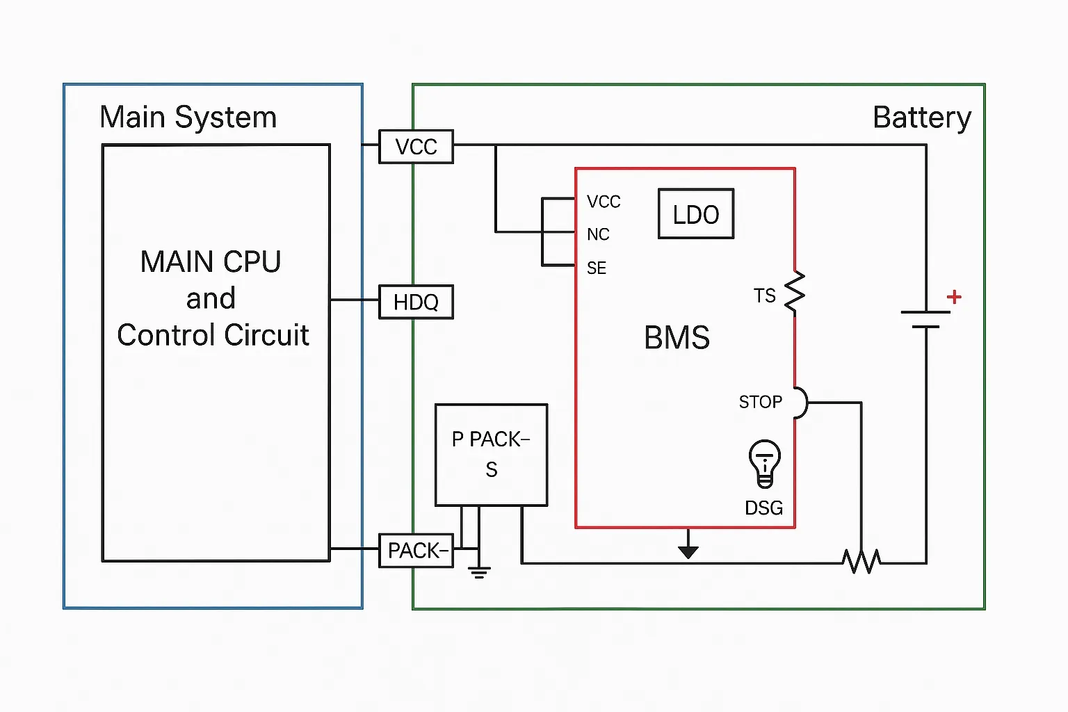
If the fuel gauge is located inside the battery pack, it can provide high-accuracy solutions using flash-based firmware and integrated 256-bit security hashing, for example BQ27Z561-R1. Protection ICs such as the BQ2970 offer voltage, current, and reverse-charge protection.
Benefits of a Smart Fuel Gauge
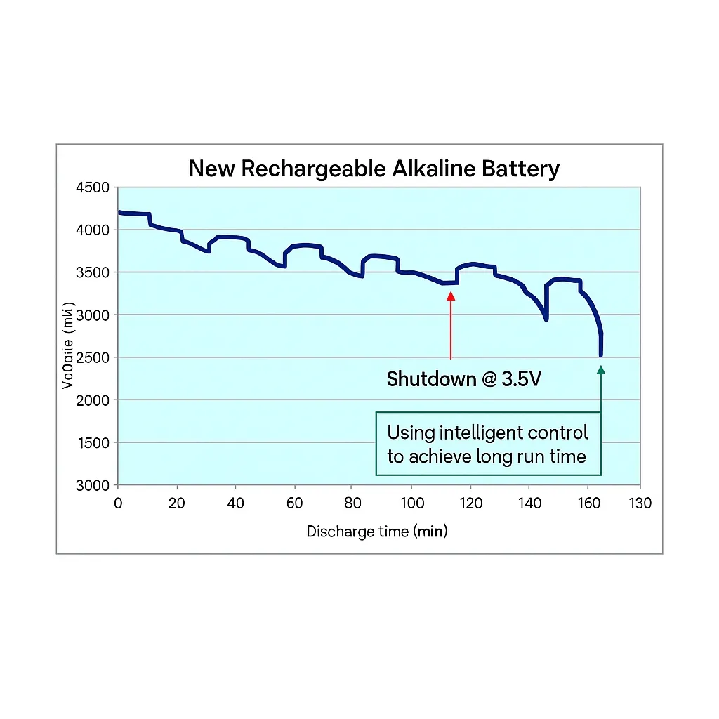
A fuel gauge raises the sophistication and intelligence of power management. Systems without an accurate fuel gauge typically shut down at a fixed voltage. Many devices shut down at around 3.5 V to preserve reserve capacity for worst-case scenarios, but measuring battery voltage only with a microcontroller and an ADC to generate a low-battery warning is not a reliable method for estimating remaining capacity because most applications have variable loads. A fuel gauge calculates remaining capacity and adjusts the shutdown voltage to meet reserve capacity requirements under any condition, thereby increasing runtime.
In addition to preserving reserve capacity, some fuel gauges avoid reporting a 0% state of charge during high transient pulse loads that can cause the battery voltage to drop below the termination threshold. This behavior is beneficial when the battery still contains significant charge, although heavy transient loads can still bring the battery to the termination voltage prematurely.
Considerations and Challenges
Batteries are complex electrochemical systems affected by aging, temperature, and impedance. Algorithm quality, compact device design, and advanced integration are key to improving system performance in battery-powered medical applications.
What are the main challenges you face with battery-powered medical devices such as continuous glucose monitors? Please share your views at the end of the article.