 ALLPCB


Overview
Control development for power electronics typically involves both power-stage design and the implementation of control software on a microcontroller. Few developers are equally skilled across all disciplines to design every part of a system at the same high quality. Electrical engineers often lack formal software engineering training: during their studies many write small programs in C or scripting languages, but only a minority participate in large software projects and follow structured programming principles.
In practice, electrical engineers are frequently tasked with programming embedded microcontrollers because they understand power electronics and system-level requirements, and are familiar with on-chip peripherals such as PWM generators and ADCs. The downside is that when the code compiles, the system runs as expected, and tests pass, development is often considered finished. Under time-to-market pressure there is little intrinsic incentive to produce reusable, maintainable code for the product lifecycle.
Consequently, handwritten codebases often lack modularity, clear structure, and documentation. For external engineers it can be difficult to determine what the code implements. Even the original author may struggle to understand their own code years later. Therefore it is useful to let engineers focus on electronics and control design, and to delegate software architecture and implementation either to experienced software developers or to automated code generation tools.
Modeling Controls as Block Diagrams
Block diagrams that represent signal flow are a natural and clear way to visualize control systems. Functional units that belong together can be encapsulated as subsystems to hide complexity and create hierarchies. Many control and simulation tools are based on block-diagram modeling.
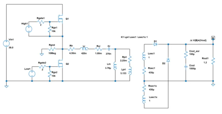
PLECS was developed primarily to accelerate simulation of power electronic circuitry, but it also provides a broad set of signal-processing modules for control-system design. The library includes continuous and discrete transfer functions, discontinuous and nonlinear modules, coordinate transformations, phase-locked loops, and PI/PID controllers commonly required in power-electronics applications. Figure 1 shows a block-diagram of a current controller used in a solar inverter, including a resonant integrator and anti-reset saturation.
Like similar tools, block diagrams designed in PLECS can be converted to equivalent C code. The generated code can be compiled and executed on different targets such as microcontrollers. Automatically generating control code from the block-diagram model, rather than using the model only for offline simulation and manually implementing code, offers several advantages:
- Control engineers can focus on functionality rather than low-level implementation details.
- Fewer specialized embedded software developers are required for initial implementation.
- Models can be modified late in the development process.
- The model serves as clear documentation.
- The model and its implementation remain synchronized.
There are also limitations to model-based code generation:
- The model must include additional information about data types, sampling rates, and task scheduling.
- Tools for diffing block-diagram models are still maturing.
- Users relinquish direct control over low-level implementation details and certain optimizations.
- Not all low-level features are always available as model components.
Automatic code generation will be adopted only if it speeds and simplifies development from the start. The time saved depends heavily on the toolchain. PLECS together with a code-generation tool provide an integrated route for embedded code generation.
Accessing I/O Peripherals
In microcontroller projects the difficult part is often not the control algorithm itself, but configuring and accessing the microcontroller's I/O peripherals. Before generating PWM in an interrupt-driven control loop and acquiring ADC readings, engineers typically need to consult extensive datasheets. Learning this for a new microcontroller family can be time consuming, and naming conventions and implementation details differ between vendors even for similar peripherals.
For an efficient workflow that involves automatic code generation, it is insufficient to convert only the algorithmic, target-independent parts of a block diagram into C and then import the generated code into a target-specific project. That approach still requires users to write and maintain glue code to address target-specific peripherals, which is manual and error-prone. For a one-step, fully automated workflow, all information about target peripherals must be included in the model. Peripherals can be represented in the model by modules that act as signal sources or sinks during simulation. During code generation these modules inject target-specific code to configure the peripheral and provide access to data.
Target Blocks in PLECS
For selected microcontroller families common in power-electronics applications, target support packages (TSPs) provide target blocks that represent various on-chip peripherals. Target blocks are visually distinct from other control blocks by their rounded corners.
Each target block provides a dialog to configure the corresponding hardware peripheral. For an analog input, users can select the ADC unit, input channel, scaling, offset, and acquisition time window. Since each acquisition is triggered by an event such as a timer, users can also specify the trigger source. Instead of setting individual bits in registers, users select options at a higher abstraction level. While options differ between microcontroller series and not all resources are available on every chip, the hardware abstraction provided by target blocks makes it easier to port a model to another microcontroller.
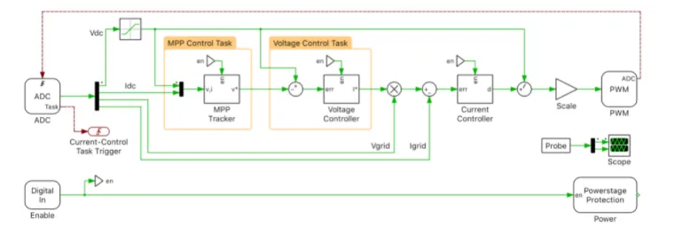
Target blocks do not only provide intuitive access to digital and analog inputs or outputs. They can combine multiple peripherals to implement more complex functions, for example peak current control with ramp compensation and front-end blanking. Figure 3 shows a complete controller model for a solar inverter that includes target-specific peripheral modules; the current-controller subsystem contains the model shown in Figure 1.
Looking under the hood of a target block reveals two complementary implementations. One is text-based and contains meta code written in the Lua scripting language; it is used to generate on-chip peripheral configuration code from dialog entries. The other is a PLECS model used to simulate the peripheral behavior during offline simulation. For an ADC, the offline model typically consists of a triggered sample-and-hold element and a quantizer.
Code Generation Subsystems
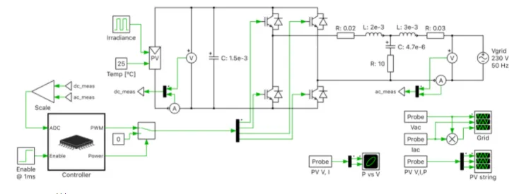
To utilize the offline models of I/O peripherals, controls must be packaged with target blocks inside a subsystem. When a target block that represents a data source (for example an ADC) is placed inside a subsystem, input terminals are added to the subsystem block. These inputs can be connected to signal sources outside the control subsystem, such as measurements from a circuit model. Similarly, target modules that represent data endpoints (for example a PWM generator) create output terminals in the subsystem. These outputs can drive gate signals for semiconductor switches in the power circuit. Grouping controls inside a subsystem does not adversely affect control-code generation, since the code generator can be instructed to generate code for a single subsystem only. Using this approach, the same model can be used for offline simulation and for code generation without modification, ensuring model and code synchronization. Figure 4 shows the overall power-circuit model of the solar inverter, where the controller from Figure 3 is contained in a code-generation subsystem.
Event-based Task Execution
When a microcontroller is used to close control loops in power electronics, current and voltage measurements are typically acquired synchronously with PWM generation. Synchronous sampling minimizes switching-harmonic content in current and voltage samples. In most digital current-control loops the PWM generator periodically triggers the ADC to sample the analog measurements. When the ADC completes a conversion it signals the presence of a new digital value by triggering an interrupt. The interrupt service routine computes control algorithms using the newly acquired values and passes updated duty cycles to the PWM generator.
PLECS introduces a special signal type to define and visualize the propagation of trigger events. To model the control loop described above, users first select the condition for the PWM generator to emit a trigger event, for example counter underflow or overflow. The PWM generator's trigger output is then connected to the ADC module's trigger input to control acquisition timing. To indicate that the control task should be executed after each conversion, the ADC's trigger output is connected to a special "control-task trigger" block.
Multitasking Environments
A single control loop is often insufficient to control an inverter or a motor drive. Cascade structures with a fast inner current-control loop and slower outer loops for voltage or speed regulation are common. Outer-loop computations may be relatively time-consuming, while simple current-control tasks are usually fast. Because current control is highly dynamic, it must run at a higher execution rate. To make efficient use of the microcontroller's compute resources, a cascaded control scheme can be implemented using preemptive rate-monotonic multitasking, where the fast current-control task interrupts slower outer-loop computations. The control model must be partitioned into multiple tasks with different sampling rates and interrupt priorities.
In PLECS this partitioning is performed graphically using frames: each frame contains a set of blocks and references a specific task defined in the encoder settings. If the target is a multicore processor, individual tasks can be assigned to different cores. In Figure 3 yellow frames assign separate tasks to the maximum-power-point tracker and the voltage regulator, which run at lower sampling rates than the rest of the control system.
Blocks that must be computed in the same task do not necessarily have to be placed in the same frame. Because multiple frames can reference the same task, assigning blocks to different frames does not interfere with the logical structure of the control system. Other embedded code-generation tools use subsystems or special blocks to separate tasks; reusing these constructs for multiple purposes can be confusing. Task frames in PLECS make it immediately apparent which blocks share implementation-specific properties.


