 ALLPCB


Introduction
The shift to lead-free solder in automotive PCBs represents a critical evolution in automotive electronics manufacturing, driven by global environmental regulations and sustainability goals. RoHS compliance mandates the restriction of hazardous substances like lead, pushing the industry toward tin-based alloys such as SAC305. While this transition reduces environmental impact by minimizing toxic waste in landfills and during recycling, it introduces reliability challenges unique to automotive applications, where PCBs endure extreme temperatures, vibrations, and thermal cycling. Automotive PCB lead-free solder adoption requires careful process optimization to maintain the high dependability demanded by safety-critical systems like engine controls and advanced driver-assistance features. Engineers must balance these environmental imperatives with proven performance, ensuring solder joints withstand long-term operational stresses. This article explores the technical principles, practical solutions, and best practices for successful implementation.
Why Lead-Free Solder Matters in Automotive Electronics
Lead-free solder became essential following RoHS compliance requirements, which limit lead content to trace levels in electronic assemblies sold in regulated markets. In automotive electronics manufacturing, this means replacing traditional SnPb eutectic alloys with higher-melting-point alternatives, promoting recyclability and reducing health risks from lead exposure during production and end-of-life disposal. Automotive PCBs operate in harsh environments, including under-hood temperatures exceeding 125°C and rapid thermal transients, making reliability non-negotiable. The move to lead-free supports broader sustainability efforts, aligning with industry trends toward greener manufacturing without compromising vehicle safety standards. However, exemptions exist for certain high-reliability automotive applications, allowing case-by-case evaluations where lead-free risks outweigh benefits. Ultimately, proactive adoption enhances supply chain resilience amid tightening global regulations.
Technical Principles of Lead-Free Soldering in Automotive PCBs
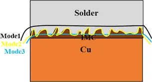
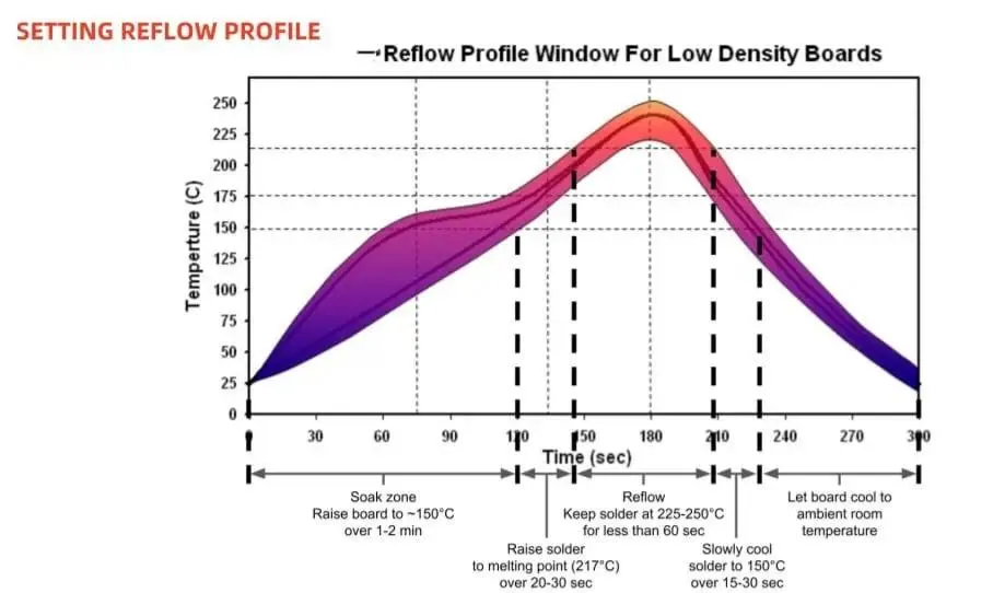
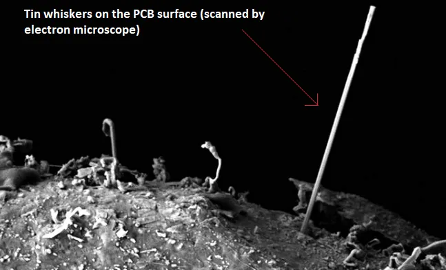
Lead-free solders, primarily tin-silver-copper compositions, exhibit a melting range around 217°C to 220°C, necessitating reflow profiles with peak temperatures 30°C to 40°C higher than leaded counterparts. This elevated automotive PCB soldering process stresses components, boards, and laminates, potentially causing warpage, delamination, or pad cratering due to mismatched coefficients of thermal expansion. Intermetallic compound (IMC) formation at the solder-pad interface accelerates with prolonged high-temperature exposure, leading to thicker, more brittle layers that reduce joint ductility under fatigue. Tin whiskers pose another concern, as pure tin finishes on components or boards can develop conductive filaments over time, risking shorts in densely packed automotive modules. These mechanisms demand precise control of preheat, soak, and reflow zones to minimize defects. Understanding these principles guides engineers in mitigating risks through material selection and process validation.
The automotive PCB soldering process for lead-free alloys requires nitrogen atmospheres to improve wetting and reduce oxidation, as tin oxidizes more readily than leaded solders. Higher liquidus temperatures extend time above liquidus, promoting IMC growth that can embrittle joints during vibration-induced fatigue. Reliability testing per IPC-9701 reveals that lead-free joints may show earlier crack initiation in thermal cycling compared to leaded, though optimized alloys close the gap. Tin whiskers emerge from compressive stresses in tin plating, exacerbated by automotive humidity and temperature swings. Factory-driven insights emphasize surface finish compatibility, such as ENIG or OSP, to suppress whisker propensity. These technical hurdles underscore the need for holistic design and assembly strategies.
Challenges to Lead-Free Solder Reliability in Automotive Applications
Lead-free solder reliability in automotive PCBs hinges on withstanding mechanical shocks, thermal cycling from -40°C to 150°C, and humidity exposure over 15-year lifecycles. Brittle fracture modes dominate due to the absence of lead's ductility, with solder joints prone to early failure under drop or vibration tests. IMC thickness control is paramount, as excessive growth weakens the joint interface, accelerating fatigue in power modules or sensors. Tin whiskers remain a persistent issue, particularly on matte tin finishes, where whiskers up to several millimeters can bridge circuits in sealed ECUs. Environmental concerns drive adoption, yet reliability data indicates lead-free requires enhanced qualification to match leaded performance. Balancing these demands involves rigorous process windows and material vetting.
Head-in-pinhole soldering and selective wave processes adapt differently for lead-free, with flux activation critical to prevent bridging or voids. Automotive electronics manufacturing profiles must avoid overheating, which exacerbates head-in-pillow defects where solder balls fail to fully collapse. Long-term reliability hinges on alloy selection, as low-silver variants offer cost benefits but trade off creep resistance. Standards like IPC J-STD-001 provide criteria for void limits and fillet formation, ensuring class 3 assemblies meet automotive rigor. These challenges highlight the factory's role in iterative profiling and inline monitoring.
Best Practices for Automotive PCB Lead-Free Solder Implementation
Optimizing the automotive PCB soldering process starts with reflow profile development, targeting peak temperatures of 245°C to 260°C with controlled ramp rates to minimize thermal gradients. Use high-reliability fluxes designed for lead-free, offering superior activation without corrosive residues post-reflow. Surface finishes like immersion silver or ENIG pair effectively with lead-free solder, reducing IMC overgrowth and tin whisker risks through barrier layers. Conformal coatings or encapsulation mitigate whiskers in high-risk areas, while alloying tin with 2-3% bismuth suppresses growth without compatibility issues. Validate processes via thermal cycling and vibration per IPC-9701 to confirm joint integrity.
Component preconditioning per J-STD-020 prevents moisture-induced popcorning during reflow, a common pitfall in humid automotive supply chains. Factory best practices include stencil design with 1:1 aperture-to-pad ratios for optimal paste release and inline X-ray for void inspection. For wave soldering, titanium liners extend pot life, maintaining alloy consistency. Reliability enhancements involve doping with minor elements like nickel to refine microstructure and boost fatigue life. These measures ensure RoHS compliance without sacrificing performance.
Troubleshooting focuses on common defects like tombstoning, addressed by balanced preheat to equalize component heating. Lead-free solder reliability improves with multi-nozzle reflow ovens for uniform heating across large panels. Documentation of process capability indices guides continuous improvement. Automotive teams benefit from supplier audits ensuring J-STD-609 marking for lead-free verification. These practical steps foster robust assemblies.
Automotive-Specific Insights and Mitigation Strategies
In engine control units, tin whiskers have caused field failures, prompting mitigation via re-plating or conformal coatings during assembly. High-vibration areas demand low-standoff heights to enhance mechanical coupling. Hybrid processes combining reflow and selective soldering accommodate mixed technologies. Insights from accelerated life testing reveal that optimized lead-free profiles achieve parity with leaded in 2000-cycle thermal shock. Factory protocols include post-reflow bake-outs to stabilize IMC. These strategies align environmental goals with automotive durability.
Conclusion
Adopting lead-free solder in automotive PCBs successfully balances RoHS compliance and environmental stewardship with unwavering reliability through informed technical practices. Key to success lies in mastering higher-temperature soldering processes, controlling IMC and tin whiskers, and leveraging standards like IPC J-STD-001 and IPC-9701. Engineers achieve this via precise reflow profiling, compatible finishes, and rigorous qualification, ensuring automotive electronics manufacturing meets demanding lifecycles. As regulations evolve, proactive implementation positions manufacturers for sustainable, high-performance production. Prioritizing these elements minimizes risks while advancing greener technologies.
FAQs
Q1: What are the main reliability challenges of automotive PCB lead-free solder?
A1: Lead-free solder reliability concerns stem from higher brittleness, accelerated IMC growth, and tin whisker potential under automotive thermal cycling and vibration. Higher reflow temperatures increase board warpage risks, but mitigation via optimized profiles and finishes per IPC J-STD-001 achieves comparable performance to leaded joints. Proper alloy selection and testing ensure long-term durability in safety-critical applications.
Q2: How does RoHS compliance affect the automotive PCB soldering process?
A2: RoHS compliance mandates lead-free solder, requiring elevated reflow peaks and nitrogen atmospheres for wetting in automotive PCB soldering processes. This shifts profiles upward, demanding robust components and laminates to avoid defects like cratering. Exemptions apply selectively, but full adoption enhances sustainability. Validation through thermal profiling maintains joint integrity.
Q3: What mitigation strategies address tin whiskers in lead-free automotive electronics?
A3: Tin whiskers in lead-free solder arise from pure tin finishes; mitigate with alloyed platings like matte tin-bismuth, nickel underlayers, or conformal coatings. Automotive electronics manufacturing benefits from J-STD-020 preconditioning and encapsulation. Accelerated testing confirms suppression over lifecycles, preventing shorts in dense modules.
Q3: Why is lead-free solder reliability critical for automotive PCBs?
A3: Lead-free solder reliability ensures automotive PCBs withstand -40°C to 150°C swings and vibrations without fatigue failure. Despite brittleness challenges, best practices like controlled IMC and whisker mitigation per IPC-9701 deliver proven performance. This upholds safety in ECUs and sensors while meeting RoHS compliance.
References
IPC J-STD-001 — Requirements for Soldered Electrical and Electronic Assemblies. IPC, 2017
IPC-9701 — Performance Test Methods and Qualification Requirements for Surface Mount Solder Attachments. IPC, 2011
J-STD-020E — Moisture/Reflow Sensitivity Classification for Nonhermetic Surface Mount Devices. JEDEC/IPC, 2014


