 ALLPCB


Printed circuit boards (PCBs) are the backbone of modern electronics, connecting components to create functional devices. Whether you're designing a smartphone, a medical device, or an automotive system, choosing the right PCB type is critical. Rigid, flexible, and rigid-flex PCBs each offer unique advantages, but their differences in design, materials, and applications can significantly impact your project's success. In this blog, we'll break down these three PCB types, providing engineers with actionable insights to make informed decisions.
Our goal is to clarify the distinctions between rigid, flexible, and rigid-flex PCBs, exploring their construction, benefits, and ideal use cases. By the end, you'll have a clear understanding of which PCB type suits your application and how to optimize your design for performance and reliability.
What Are Rigid PCBs?
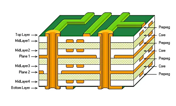
Rigid PCBs are the most common type of circuit board, characterized by their solid, inflexible structure. These boards are typically made from a glass-reinforced epoxy laminate, such as FR-4, which provides mechanical strength and thermal stability. Rigid PCBs are designed to maintain their shape, making them ideal for applications where components need a stable mounting surface.
Key Features of Rigid PCBs
- Material Composition: FR-4 is the standard substrate, with a dielectric constant of approximately 4.5 at 1 MHz, ensuring stable electrical performance. Copper traces, often 1-2 oz/ft² thick, form the conductive pathways.
- Layer Count: Rigid PCBs can range from single-sided (one copper layer) to multilayer designs with 20+ layers, supporting complex circuits.
- Cost-Effectiveness: Rigid PCBs are generally less expensive to manufacture due to mature fabrication processes and high-volume production capabilities.
Applications
Rigid PCBs dominate in consumer electronics like TVs, desktop computers, and home appliances. Their rigidity ensures reliable component support in larger devices where space constraints are less critical. For example, a desktop motherboard may use a 6-layer rigid PCB to handle high-speed signals with controlled impedance of 50 ohms for USB 3.0 interfaces.
What Are Flexible PCBs?
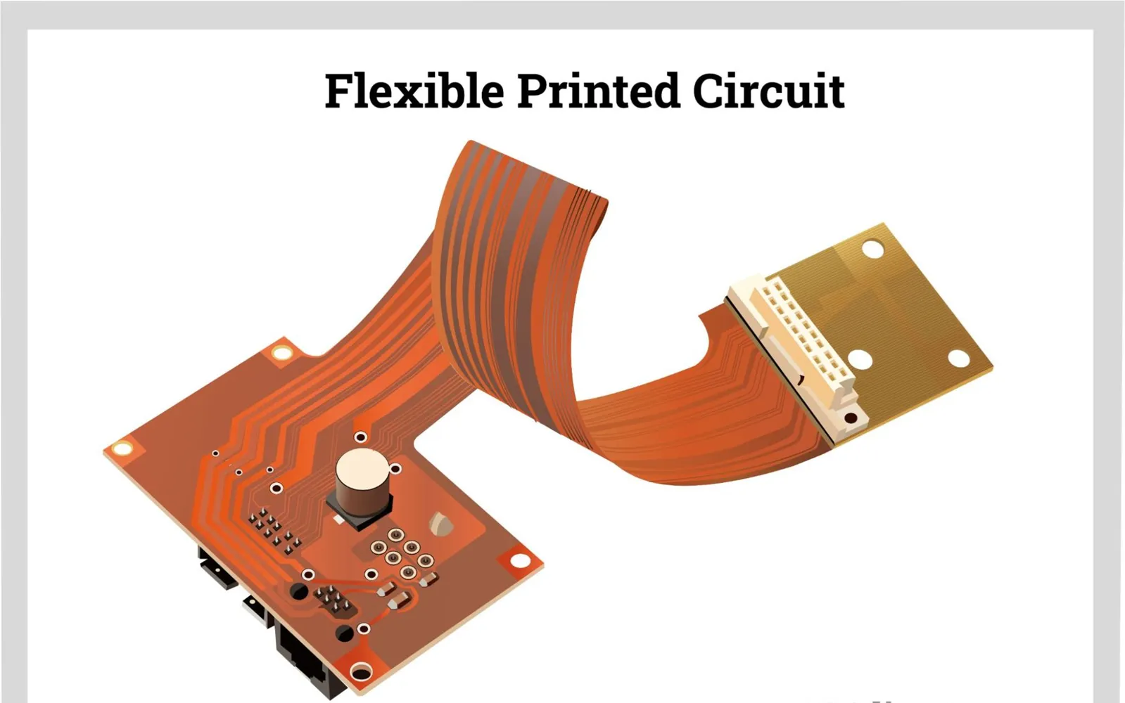
Flexible PCBs, or flex circuits, are built on pliable substrates like polyimide, allowing them to bend, fold, or twist without damaging the circuitry. These boards are thinner and lighter than rigid PCBs, making them ideal for compact or dynamic applications.
Key Features of Flexible PCBs
- Material Composition: Polyimide substrates, with a dielectric constant of around 3.4, offer excellent thermal resistance (up to 400°C) and flexibility. Rolled annealed copper, typically 0.5-1 oz/ft², is used for conductive traces to withstand bending.
- Bendability: Flex PCBs can achieve a bend radius as low as 0.1 mm for single-layer designs, enabling tight folds in confined spaces.
- Durability: Flex circuits can endure hundreds of thousands of flex cycles, making them suitable for dynamic applications like foldable displays.
Applications
Flexible PCBs shine in wearable devices, smartphones, and medical implants. For instance, a smartwatch may use a double-sided flex PCB to connect its display and battery, fitting within a 1.5 mm thick enclosure while maintaining signal integrity for 5G connectivity at 3.5 GHz.
Explore use cases in:
- Flexible PCB Design for Medical Wearables: Balancing Performance and Biocompatibility
- Flexible PCBs for Foldable Phones: Design and Manufacturing Innovations
What Are Rigid-Flex PCBs?
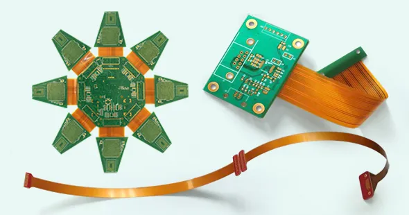
Rigid-flex PCBs combine the best of both worlds, integrating rigid and flexible substrates into a single board. Flexible layers, typically polyimide, are sandwiched between or connected to rigid FR-4 sections, creating a hybrid design that offers both structural stability and flexibility.
Key Features of Rigid-Flex PCBs
- Hybrid Construction: The rigid-flex PCB often has 4-12 layers, with flexible layers (0.05-0.1 mm thick) bonded to rigid sections (0.8-1.6 mm thick) using epoxy or acrylic adhesives.
- Space Efficiency: By eliminating connectors and cables, rigid-flex designs reduce system volume by up to 50% compared to interconnected rigid boards.
- Reliability: Integrated flex layers reduce solder joints, lowering failure rates in high-vibration environments (e.g., 20G shock resistance for aerospace applications).
Applications
Rigid-flex PCBs are ideal for complex, high-reliability applications like aerospace, medical devices, and automotive systems. For example, a pacemaker may use a rigid-flex PCB with two rigid sections for component mounting and a flexible section to conform to the device's curved housing, ensuring a compact 10 cm³ package.
Comparing Rigid, Flexible, and Rigid-Flex PCBs
To help engineers choose the right PCB type, let's compare their key characteristics:
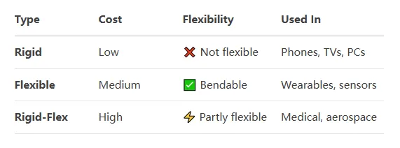
| Feature | Rigid PCB | Flexible PCB | Rigid-Flex PCB |
|---|---|---|---|
| Material | FR-4, glass epoxy | Polyimide, Kapton | FR-4 + Polyimide |
| Flexibility | None | High (bend radius ~0.1 mm) | Partial (flexible sections) |
| Layer Count | 1-20+ | 1-8 | 4-12+ |
| Cost | Low | High | Highest |
| Weight | Heavy (~1.5 g/cm² for FR-4) | Light (~0.2 g/cm² for polyimide) | Moderate |
| Vibration Resistance | Moderate (5-10G) | High (10-20G) | High (15-20G) |
| Applications | TVs, PCs, appliances | Wearables, smartphones | Aerospace, medical, automotive |
Performance Considerations
- Signal Integrity: Rigid PCBs support high-speed signals (e.g., PCIe 4.0 at 16 GT/s) due to their stable dielectric properties. Flexible PCBs may require careful impedance control (e.g., 100 ohms differential) to avoid signal degradation in high-frequency applications.
- Thermal Management: Rigid PCBs offer better heat dissipation (thermal conductivity ~0.3 W/m·K for FR-4) than flex PCBs (~0.2 W/m·K for polyimide). Rigid-flex designs balance both, with rigid sections handling heat-generating components.
- Component Density: Rigid-flex PCBs enable higher component density (up to 200 components/cm²) by utilizing both sides of the board and eliminating connectors.
Advantages and Challenges of Each PCB Type
Rigid PCBs
- Advantages: Cost-effective, easy to manufacture, and suitable for high-layer-count designs. They provide robust mechanical support for heavy components like transformers.
- Challenges: Lack of flexibility limits their use in compact or dynamic applications. Large rigid PCBs (e.g., 15" x 20") can be complex to route, increasing via count and cost.
Flexible PCBs
- Advantages: Lightweight and adaptable, flex PCBs reduce system weight by up to 70% compared to rigid boards. Their durability suits dynamic flexing (e.g., 500,000 cycles in foldable phones).
- Challenges: Higher manufacturing costs and limited layer counts (typically 1-8) restrict their use in complex circuits. Repairs are difficult due to delicate substrates.
Rigid-Flex PCBs
- Advantages: Combine stability and flexibility, reducing part count and improving reliability. They support 3D designs, enabling innovative form factors like folded IoT modules.
- Challenges: Complex fabrication processes increase costs and lead times. Designers must account for bend radius limitations (e.g., 10x the flex thickness) to avoid cracking.

Choosing the Right PCB for Your Project
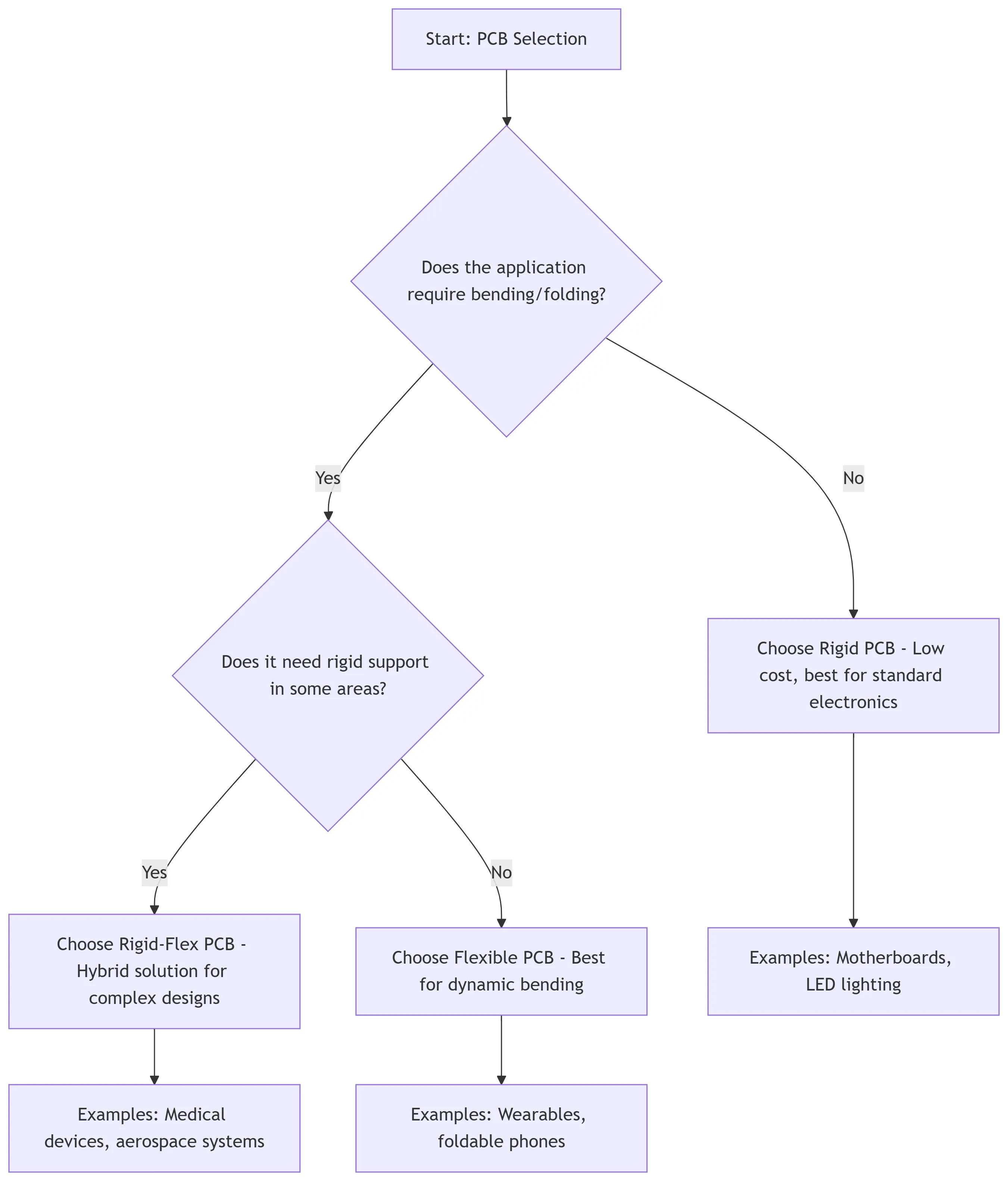
Selecting the appropriate PCB type depends on your application's requirements:
- Use Rigid PCBs for cost-sensitive, high-volume products with minimal space constraints, such as home appliances or industrial controllers. Their affordability and scalability make them ideal for standard designs.
- Use Flexible PCBs for compact, lightweight devices requiring dynamic flexing, like wearables or foldable electronics. Ensure your design accounts for impedance control and flex cycle durability.
- Use Rigid-Flex PCBs for high-reliability applications with complex geometries, such as aerospace or medical devices. Their hybrid nature optimizes space and performance but requires careful planning to manage costs.
Design Tips
- Impedance Control: For high-speed signals, maintain consistent trace widths (e.g., 5 mils for 50-ohm single-ended traces) across all PCB types.
- Bend Radius: For flex and rigid-flex PCBs, ensure the bend radius is at least 6-10 times the flex thickness to prevent trace damage.
- Thermal Management: Place heat-generating components on rigid sections of rigid-flex PCBs to leverage FR-4's thermal conductivity.
How ALLPCB Supports Your PCB Needs
At ALLPCB, we understand the complexities of designing and manufacturing rigid, flexible, and rigid-flex PCBs. Our advanced manufacturing facilities and quick-turn prototyping services ensure engineers can iterate designs rapidly, meeting tight project deadlines. With global logistics and expertise in high-density interconnects (HDI), we deliver high-quality PCBs tailored to your specifications, whether you're developing a compact wearable or a robust aerospace system. Our team supports you from design to delivery, ensuring reliability and performance for your next project.
Conclusion
Rigid, flexible, and rigid-flex PCBs each serve distinct purposes in the world of electronics. Rigid PCBs offer cost-effective stability for traditional applications, flexible PCBs enable lightweight and dynamic designs, and rigid-flex PCBs provide a versatile hybrid solution for complex, high-reliability systems. By understanding their differences—materials, performance, and applications—engineers can make informed choices to optimize their designs.
When embarking on your next project, consider your application's mechanical, electrical, and environmental requirements. Whether you need the robustness of rigid PCBs, the adaptability of flex circuits, or the hybrid benefits of rigid-flex, choosing the right PCB type is the first step toward success. Let us know your thoughts or questions in the comments below, and stay tuned for more insights on PCB design and manufacturing.


