 ALLPCB


Are you facing challenges with integrated circuits (ICs) in your printed circuit board (PCB) assembly? Whether it's identifying faulty ICs, conducting failure analysis, or applying effective repair techniques, troubleshooting ICs can be a daunting task. In this comprehensive guide, we'll walk you through practical steps and methods to diagnose and resolve PCB assembly defects related to ICs. From IC testing methods to PCB repair techniques, this blog covers everything you need to streamline your troubleshooting process and ensure reliable performance.
Why IC Troubleshooting Matters in PCB Assembly
Integrated circuits are the heart of modern electronics, acting as the brain that controls functionality in devices ranging from smartphones to industrial machinery. However, when an IC fails or malfunctions during PCB assembly, it can lead to significant delays, increased costs, and compromised product quality. Understanding how to troubleshoot ICs effectively is crucial for engineers and technicians to minimize downtime and maintain high standards in production.
In this guide, we'll dive deep into identifying common PCB assembly defects, performing IC failure analysis, and using proven IC testing methods to pinpoint issues. Let's start with the basics of what causes IC-related problems in PCB assembly.
Common Causes of IC Failures in PCB Assembly
Before diving into troubleshooting techniques, it's important to understand why ICs fail in the first place. Here are some of the most common reasons for IC-related PCB assembly defects:
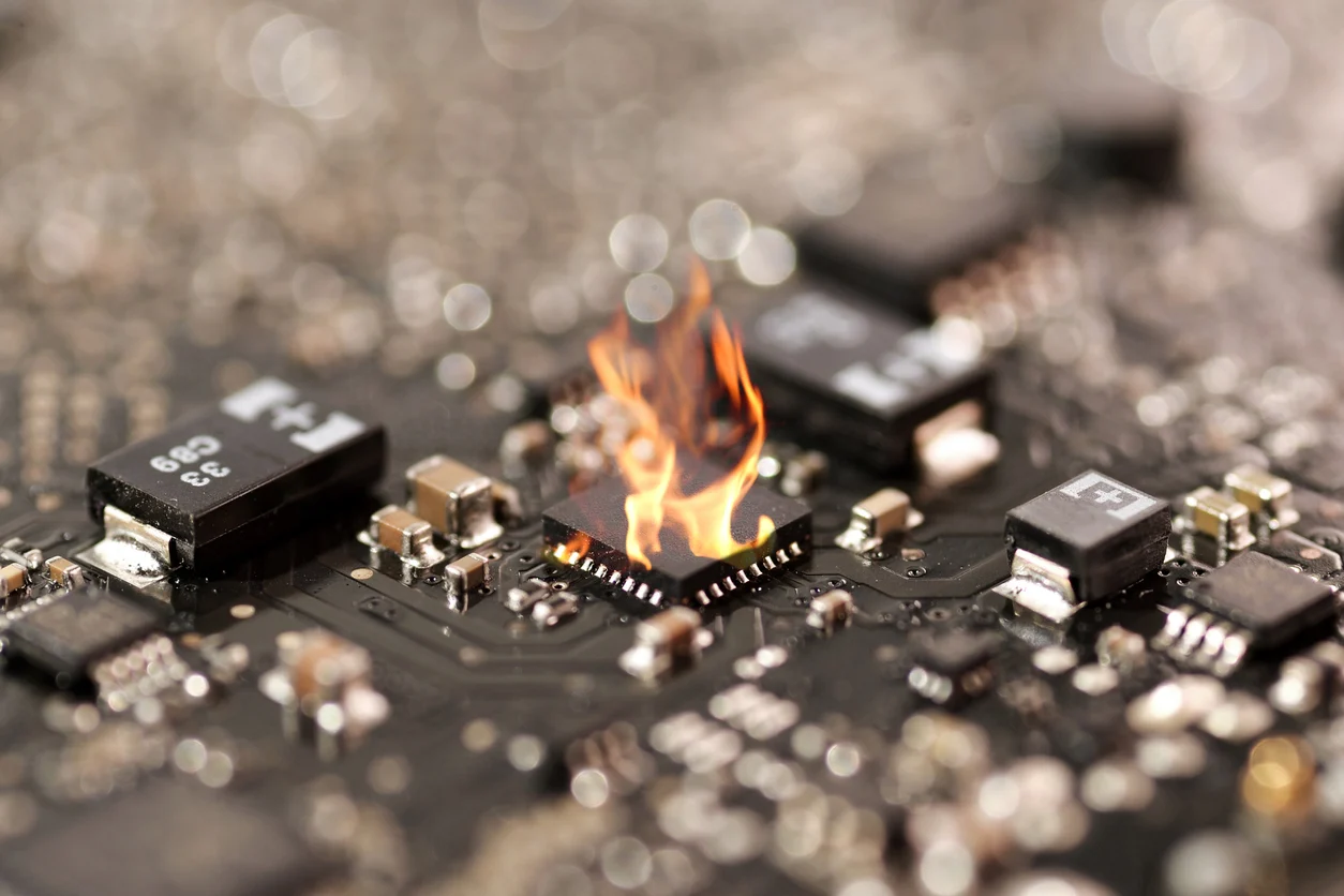
- Thermal Stress: Excessive heat during soldering or operation can damage ICs, causing cracks or internal failures. For instance, reflow soldering at temperatures above 260°C for prolonged periods can degrade IC components.
- Electrostatic Discharge (ESD): A sudden discharge of static electricity can destroy sensitive IC components. Even a small discharge of 100 volts can be catastrophic for some chips.
- Poor Soldering Practices: Issues like cold solder joints or insufficient solder can lead to poor connections, causing intermittent failures or complete IC malfunction.
- Mechanical Damage: Physical stress during handling or assembly can crack IC packages or dislodge internal connections.
- Power Supply Issues: Overvoltage or undervoltage conditions can damage ICs. For example, supplying 5.5V to a chip rated for 5V can cause irreversible harm.
- Manufacturing Defects: Internal flaws in the IC itself, such as defective silicon or poor packaging, can lead to failures even under normal operating conditions.
Understanding these root causes helps in both preventing issues and narrowing down the problem during troubleshooting. Now, let's explore how to identify faulty ICs on a PCB.
Identifying Faulty ICs: Key Signs and Symptoms
Finding a defective IC on a densely populated PCB can feel like searching for a needle in a haystack. However, there are telltale signs that can guide you to the culprit. Here's what to look for when identifying faulty ICs:
- Overheating: If an IC feels excessively hot to the touch or shows a temperature reading above its specified limit (often found in the datasheet), it may be malfunctioning.
- No Output or Incorrect Output: Use a multimeter or oscilloscope to check if the IC is producing the expected voltage or signal. For instance, a logic gate IC should output a clear high (e.g., 5V) or low (e.g., 0V) signal based on input conditions.
- Visible Damage: Look for cracks, burns, or discoloration on the IC package. These are clear indicators of physical or thermal damage.
- Intermittent Behavior: If the PCB works sporadically or fails under specific conditions (like after warming up), the IC might be the issue.
- Power Consumption Anomalies: A sudden spike or drop in current draw (measured using a multimeter in series with the power supply) can point to a failing IC.
IC Testing Methods for Accurate Diagnosis
Once you suspect an IC is faulty, the next step is to test it using reliable methods. Here are some proven IC testing methods to confirm defects during PCB assembly troubleshooting:
1. Visual Inspection
Start with a thorough visual check using a magnifying glass or microscope. Look for physical damage, poor solder joints, or signs of overheating on the IC and surrounding components. This method is quick and often reveals obvious issues like cracked packages or burnt pins.
2. Multimeter Testing
A digital multimeter is an essential tool for basic IC testing. Set it to continuity mode to check for short circuits or open connections between pins. Alternatively, use voltage mode to measure input and output voltages against the IC's datasheet specifications. For example, if a regulator IC rated for 3.3V output shows only 2.5V, it's likely defective.
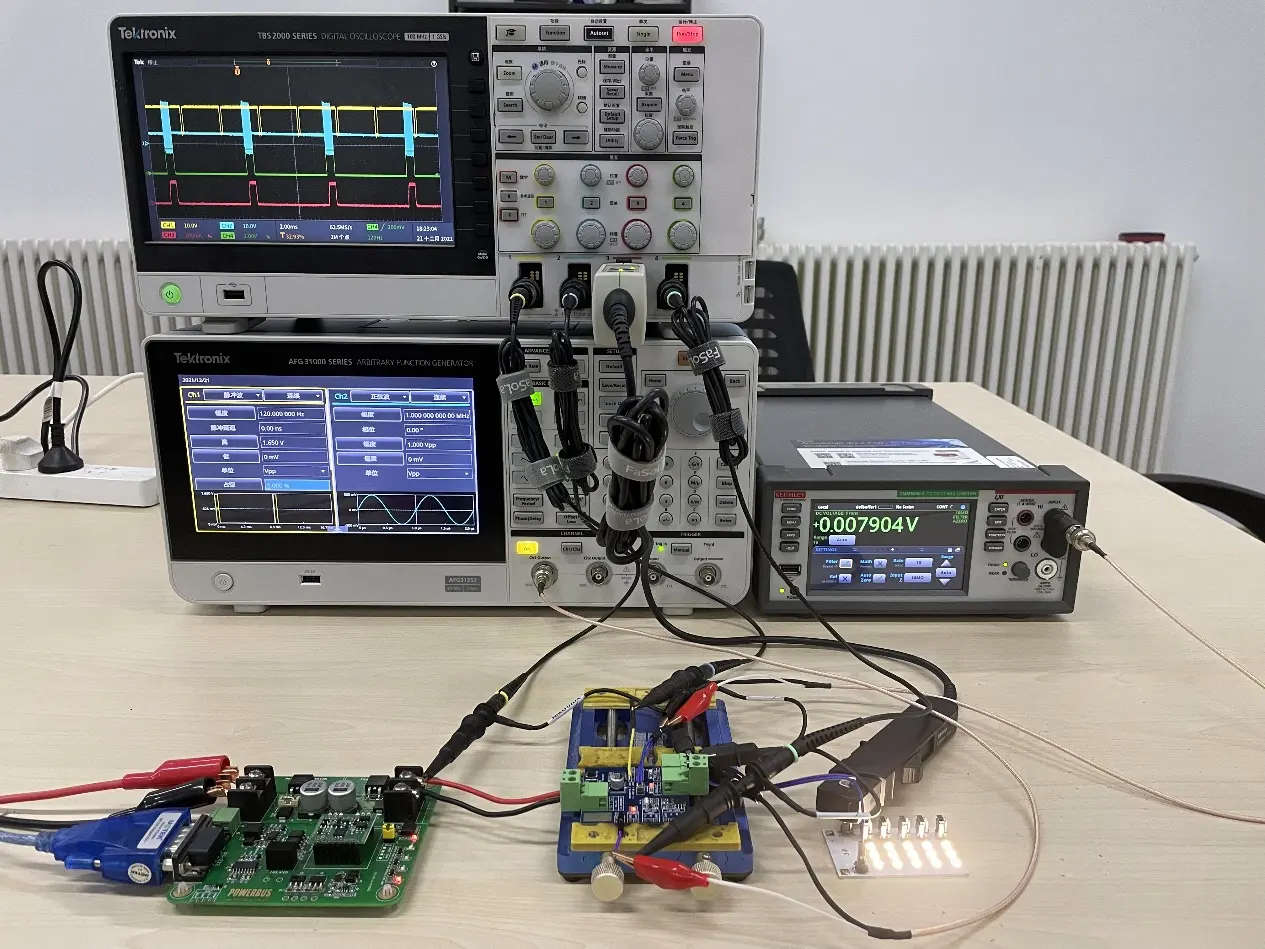
3. Oscilloscope Analysis
For ICs handling signals (like amplifiers or microcontrollers), an oscilloscope helps analyze waveforms. Check if the output signal matches the expected frequency and amplitude. A distorted waveform or no signal at all often indicates an internal IC failure.
4. In-Circuit Testing (ICT)
In-circuit testing uses specialized equipment to test ICs without removing them from the PCB. ICT systems apply test signals to specific pins and measure responses, helping to isolate faulty components on complex boards.
Recommended Reading: In-Circuit Testing (ICT): Validating PCB Functionality at Scale
5. Functional Testing
Power up the PCB and test the IC's functionality within the circuit. For instance, if it's a microcontroller, upload a simple test program to see if it executes correctly. Failure to perform as expected points to an issue with the IC or its connections.
IC Failure Analysis: Digging Deeper into the Problem
Once you've identified a faulty IC, conducting a detailed failure analysis helps understand why it failed and how to prevent similar issues. IC failure analysis involves a systematic approach to uncover root causes. Here's how to do it:
- Document the Symptoms: Note down all observed issues, such as error codes, overheating, or signal loss. This creates a baseline for analysis.
- Check Environmental Factors: Review the operating conditions. Was the PCB exposed to high humidity, extreme temperatures, or ESD events?
- Analyze Electrical Stress: Use a multimeter to check if the IC received the correct voltage and current. Compare readings with datasheet limits.
- Inspect Physical Damage: Look for cracks or burns under magnification. In some cases, X-ray imaging can reveal internal bond wire damage, as shared by professionals on social platforms.
- Review Assembly Process: Evaluate soldering techniques, reflow profiles, and handling procedures. For example, a reflow temperature peak above 260°C for more than 30 seconds might have damaged the IC.
By combining these steps, you can pinpoint whether the failure was due to design flaws, manufacturing errors, or external factors, allowing for targeted solutions.
PCB Repair Techniques for IC Issues
After confirming an IC is faulty, the next step is repair or replacement. Here are practical PCB repair techniques to address IC-related defects:
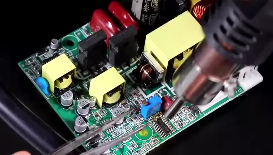
1. Desoldering and Replacing the IC
Use a hot air rework station to remove the defective IC. Set the temperature to around 300°C and direct the heat evenly over the IC for 20-30 seconds until the solder melts. Lift the IC with tweezers, clean the pads with a soldering iron and wick, and solder a new IC in place. Ensure proper alignment to avoid shorts or open connections.
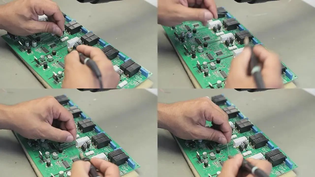
2. Fixing Solder Joints
If the issue is a poor solder joint, reflow the joint using a soldering iron at 300-350°C. Apply flux to the area, add a small amount of fresh solder, and ensure a shiny, concave joint forms. This often resolves connectivity issues without replacing the IC.
3. Addressing Trace Damage
If PCB traces near the IC are damaged, use a conductive pen or thin wire to repair small breaks. For larger damage, consider adding jumper wires to bypass the broken trace, ensuring insulation to prevent shorts.
4. Protecting Against ESD
During repairs, always work on an ESD-safe mat and wear a grounded wrist strap. This prevents further damage to the IC or other components during handling.
Preventing IC Failures in Future PCB Assemblies
While troubleshooting and repair are essential skills, preventing IC failures is even better. Here are actionable tips to minimize PCB assembly defects related to ICs:
- Use Proper Soldering Profiles: Follow the manufacturer's recommended reflow profile to avoid thermal stress. Typically, keep peak temperatures below 260°C for most ICs.
- Implement ESD Protection: Equip your workspace with ESD-safe tools and train staff on proper handling to eliminate static discharge risks.
- Verify Power Supply Stability: Use voltage regulators and filters to ensure the IC receives a stable power input within its rated range (e.g., 3.3V ± 0.3V).
- Conduct Pre-Assembly Testing: Test ICs for functionality before soldering them onto the PCB to catch defective components early.
- Choose Reliable Components: Source ICs from trusted suppliers to reduce the risk of counterfeit or substandard parts.
Tools You Need for Effective IC Troubleshooting
Having the right tools can make all the difference in diagnosing and repairing IC issues. Here's a list of essential equipment for your workbench:
- Digital Multimeter: For measuring voltage, current, and continuity.
- Oscilloscope: To analyze signal integrity and waveforms.
- Hot Air Rework Station: For desoldering and soldering ICs.
- Soldering Iron: For precise solder joint repairs (recommended tip temperature: 300°C).
- Magnifying Glass or Microscope: To inspect small components and solder joints.
- ESD-Safe Tools: Including mats, wrist straps, and tweezers to prevent static damage.
Conclusion: Mastering IC Troubleshooting for Reliable PCB Assembly
Troubleshooting integrated circuits is a critical skill for anyone involved in PCB assembly. By understanding the common causes of IC failures, recognizing the signs of faulty ICs, and applying effective testing and repair techniques, you can resolve issues efficiently and ensure the reliability of your electronic products. Whether you’re using a multimeter for basic checks or conducting detailed IC failure analysis, the methods outlined in this guide provide a practical roadmap to success.
At ALLPCB, we're committed to supporting your PCB assembly needs with high-quality solutions and expert advice. By incorporating these IC troubleshooting tips into your workflow, you’ll be better equipped to handle defects and maintain top-notch performance in every project.


