 ALLPCB


Introduction
Medical imaging equipment demands exceptional precision and reliability to produce clear diagnostic images while minimizing patient risk. Devices like MRI machines and CT scanners process high-frequency signals for data acquisition, RF transmission, and image reconstruction. Rogers PCBs excel in these environments due to their suitability as high-frequency PCB for medical applications. They provide the signal integrity needed for low noise PCB design, ensuring minimal distortion in sensitive circuits. Electrical engineers designing such systems must prioritize medical grade PCB materials that maintain performance under demanding thermal and electrical conditions. This article examines Rogers PCBs in MRI machines, Rogers PCBs in CT scanners, and key design considerations for optimal results.
Understanding Rogers PCBs for Medical Applications
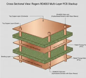
Rogers PCBs refer to printed circuit boards fabricated using specialized laminates from Rogers materials, optimized for high-frequency operations. These materials feature consistent dielectric properties, which prevent signal degradation over wide frequency ranges. In medical imaging, where signals can reach microwave frequencies, standard FR-4 laminates fall short due to higher losses and variability. Rogers PCBs address this by offering low dielectric constant and dissipation factor, making them ideal medical grade PCB materials. Engineers select them to meet the stringent requirements of imaging systems that operate continuously in controlled environments. Their mechanical stability also supports multilayer constructions common in compact medical devices.
The relevance stems from the need for reliable performance in life-critical applications. MRI and CT systems generate vast amounts of data quickly, requiring PCBs that handle high-speed digital and analog signals without introducing artifacts. Poor material choice can lead to image noise or system failures, compromising diagnostics. Rogers PCBs mitigate these risks through superior electrical characteristics tailored for high-frequency PCB for medical applications. Procurement teams value their compatibility with standard fabrication processes, easing integration into production workflows. Overall, they elevate system reliability while adhering to industry expectations for quality.
Key Technical Principles Behind Rogers PCBs in Imaging
High-frequency signals in medical imaging propagate through transmission lines on PCBs, where material properties dictate loss and impedance. Rogers laminates exhibit low loss tangent, reducing insertion loss and preserving signal amplitude across the board. This proves critical in RF front-ends, where even minor attenuation distorts received echoes. Thermal stability ensures dielectric constant remains consistent despite heat from power amplifiers or gradient coils. Engineers model these behaviors using field solvers to predict performance before fabrication.
In low noise PCB design, crosstalk and electromagnetic interference pose major challenges. Rogers materials support tight impedance control, typically 50 ohms for RF lines, minimizing reflections that amplify noise. Ground planes and via fencing further isolate sensitive traces, but material uniformity enhances effectiveness. For multilayer stacks, low coefficient of thermal expansion matches copper, preventing delamination during thermal cycling. These principles align with IPC-6012E qualification standards for rigid printed boards, ensuring boards withstand operational stresses.
Signal integrity in high-frequency PCB for medical applications relies on minimizing phase shifts and group delay variations. Rogers PCBs deliver predictable propagation velocities, vital for phased array antennas in advanced imaging. Their resistance to moisture absorption maintains performance in humid clinical settings. Fabricators drill and plate vias with precision to avoid stubs that cause resonances. Troubleshooting starts with S-parameter measurements to verify return loss below acceptable thresholds.
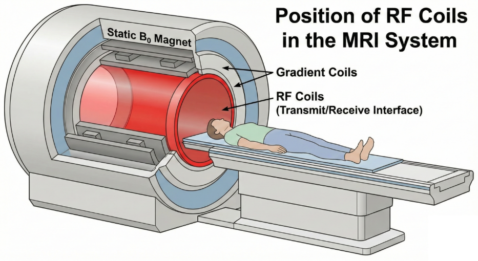
Rogers PCBs in MRI Machines
MRI machines use superconducting magnets and RF coils to excite hydrogen nuclei, producing detailed soft-tissue images. Rogers PCBs in MRI machines handle RF transmission and reception at frequencies around 64 MHz to 400 MHz. Receive chain preamplifiers demand ultra-low noise figures, where high-quality factor traces reduce thermal noise contributions. Gradient amplifier drivers process fast-switching currents, requiring stable dielectrics to avoid arcing or breakdown. These boards often integrate mixed-signal circuits, benefiting from Rogers' hybrid stackup compatibility.
Low noise PCB design techniques include embedded shielding and differential routing on Rogers substrates. Surface mount components for LNAs connect via microstrip lines optimized for minimal radiation. Engineers simulate coupling between adjacent channels to space traces adequately. Fabrication follows IPC-A-600K acceptability criteria, inspecting for voids or resin smear that could degrade Q-factor. Field-deployed systems endure vibrations, so mechanical robustness prevents microcracks.
Common troubleshooting involves debugging elevated noise floors from ground bounce. Solutions include stitching vias around noisy digital sections and using Rogers cores for analog islands. Power plane partitioning isolates RF from DC-DC converters. Post-assembly testing with network analyzers confirms vector network analyzer traces match simulations. These practices ensure Rogers PCBs in MRI machines deliver artifact-free imaging.
Rogers PCBs in CT Scanners
CT scanners rotate X-ray sources and detectors at high speeds, reconstructing 3D images from projections. Rogers PCBs in CT scanners manage data acquisition systems (DAS) operating at gigasample rates. High-frequency PCB for medical applications here focus on analog-to-digital converters and serializer-deserializer links. Low loss materials prevent eye diagram closure in serial interfaces, maintaining bit error rates below 10^-12. Detector front-ends amplify faint signals, where Rogers substrates support low-noise amplifiers with optimal gain flatness.
Thermal management challenges arise from dense packing and continuous rotation. Rogers laminates dissipate heat effectively while keeping CTE low for via reliability. Multilayer designs route high-speed LVDS pairs with length matching to avoid skew. J-STD-020E guidelines govern handling to prevent moisture-induced popcorn effects during reflow. Engineers prioritize via-in-pad for density, ensuring plating integrity per IPC standards.
Troubleshooting skew in DAS often traces to dielectric non-uniformity. Rogers materials minimize this through filled-PTFE or ceramic composites. Signal conditioning filters on-board reduce jitter. Vibration testing validates mechanical integrity under scanner dynamics. These elements make Rogers PCBs indispensable for CT performance.
Best Practices for Low Noise PCB Design with Rogers Materials
Select Rogers laminates based on frequency band and loss budget during initial design. Stackup planning allocates low-loss cores to critical layers, with FR-4 hybrids for cost in non-RF sections. Impedance calculators guide trace widths, accounting for material thickness variations. Simulate full 3D fields for transitions like bends or connectors.
Fabrication demands controlled drilling speeds to avoid smear in PTFE-based materials. Sequential lamination builds complex stacks without warpage. Solder mask selection impacts RF performance, favoring thin liquid photoimageable types. Assembly uses low-residue fluxes per J-STD-001 to preserve surfaces.
Testing protocols include thermal shock and humidity exposure to mimic clinical use. EMI compliance testing verifies shielding efficacy. Field failure analysis informs iterative improvements. These practices yield robust medical grade PCB materials implementations.
Troubleshooting Common Issues in High-Frequency Medical PCBs
Excessive insertion loss often stems from surface roughness or poor plating. Rogers surfaces require optimized desmear processes for smooth copper. Crosstalk mitigation involves guard traces and frequency-staggered routing. Noise pickup from gradients in MRI calls for mu-metal enclosures over boards.
Via resonances degrade filters; back-drilling removes stubs. Thermal runaway in power sections needs spreaders and vias. Post-mortem sectioning reveals interlaminar voids. Data logging during qualification per IPC-6012E pinpoints root causes.
Conclusion
Rogers PCBs transform medical imaging by enabling high-frequency PCB for medical applications with unmatched signal fidelity. Their role in MRI and CT systems underscores the value of low noise PCB design and medical grade PCB materials. Engineers benefit from practical guidelines that ensure reliability under stress. Adopting these approaches minimizes downtime and enhances diagnostic accuracy. Future advancements will leverage even tighter tolerances for next-generation scanners.
FAQs
Q1: Why choose Rogers PCBs in MRI machines for RF circuits?
A1: Rogers PCBs in MRI machines provide low dielectric loss essential for maintaining high Q-factors in coils and preamps. They support precise impedance control, reducing reflections that introduce noise. Thermal stability prevents detuning during scans. Fabrication aligns with IPC Class 3 for longevity in clinical use. This combination delivers cleaner signals for superior image quality.
Q2: How do Rogers PCBs in CT scanners improve data acquisition?
A2: Rogers PCBs in CT scanners handle gigabit serial links with minimal jitter thanks to stable propagation constants. Low noise PCB design techniques like partitioned planes isolate detectors from noise sources. Hybrid stacks balance cost and performance. Compliance with J-STD-020E ensures reflow reliability. Results include sharper reconstructions and faster scan times.
Q3: What makes Rogers materials ideal high-frequency PCB for medical applications?
A3: Rogers materials offer consistent Dk and Df across frequencies, vital for medical grade PCB materials. They resist environmental factors like humidity, preserving signal integrity. Mechanical properties suit multilayer builds. Low noise PCB design benefits from low CTE matching. Engineers achieve reliable operation per IPC-6012E standards.
Q4: What are key low noise PCB design tips using Rogers substrates?
A4: Prioritize ground flooding and via stitching for shielding in low noise PCB design. Route analog traces away from digital clocks on Rogers layers. Use simulations for crosstalk budgets. Select thin dielectrics for tight coupling. Bake boards pre-assembly to control moisture, following J-STD-020E.
References
IPC-6012E - Qualification and Performance Specification for Rigid Printed Boards. IPC, 2017
IPC-A-600K - Acceptability of Printed Boards. IPC, 2020
J-STD-020E - Moisture/Reflow Sensitivity Classification. JEDEC, 2014


