 ALLPCB


Introduction
PCB depaneling represents a critical final step in the manufacturing process, where individual printed circuit boards are separated from larger production panels after assembly and testing. As surface mount technology (SMT) lines demand higher throughput and precision, manual methods struggle to keep pace, leading to bottlenecks and quality inconsistencies. Automated PCB depaneling systems address these challenges by delivering consistent separation with minimal mechanical stress, enabling factories to scale production effectively. This shift not only boosts operational efficiency but also significantly cuts labor costs in high-volume environments. For electrical engineers optimizing factory floors, understanding these systems is essential to align depaneling with overall SMT workflows.
What Is PCB Depaneling and Why It Matters
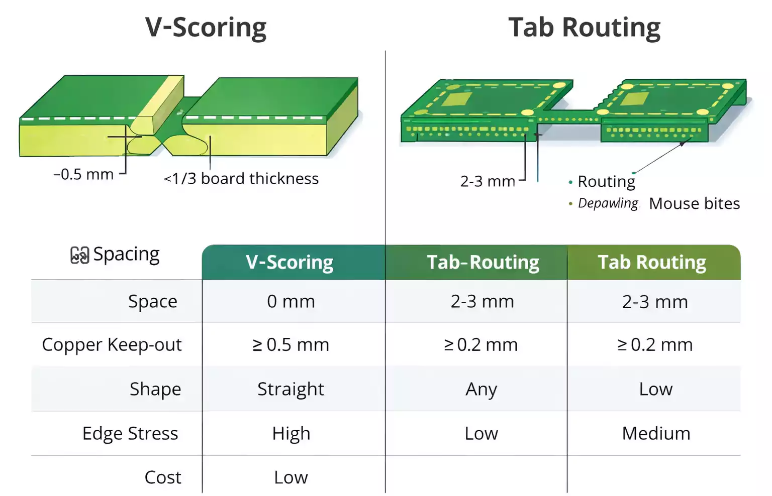
PCB depaneling involves precisely dividing a multi-board panel into single units without compromising board integrity or component functionality. Panels are typically designed with features like V-scoring, tab routing, or perforations to facilitate this separation. In modern electronics manufacturing, depaneling must minimize stress that could lead to microcracks, delamination, or solder joint failures, especially on densely populated boards with fine-pitch components. Factory-driven insights reveal that poor depaneling contributes to up to higher scrap rates and rework, directly impacting yield. Automation matters because it standardizes the process, reduces human error, and matches the takt time of upstream SMT processes. Electrical engineers benefit from this by ensuring reliable boards that meet performance specifications under operational stresses.
The relevance intensifies in high-mix, high-volume production where labor shortages and rising wages pressure margins. Manual depaneling relies on operator skill, often resulting in inconsistent edge quality and handling damage. Automated systems, conversely, provide repeatable results, supporting lean manufacturing principles. As panels grow larger to optimize material use, precise depaneling becomes vital to avoid warpage or misalignment in downstream testing and packaging.
Depaneling Machine Types
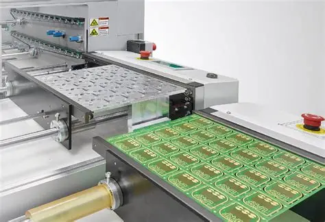
Depaneling machine types vary based on panel design, board complexity, and production volume, each offering distinct trade-offs in speed, stress, and flexibility. V-scoring machines use blades or wheels to snap along pre-grooved lines, ideal for rectangular boards with straight edges. These systems excel in simplicity and speed for high-volume runs but generate mechanical stress if not properly fixtured. Routing machines employ high-speed spindles to mill along tabbed outlines, accommodating irregular shapes and dense component layouts. They produce smoother edges than scoring but require dust extraction to prevent contamination.
Laser depaneling systems ablate material in a non-contact manner, eliminating stress entirely and enabling cuts as fine as needed for flexible or rigid-flex boards. Punching or die-cutting presses stamp boards in one motion, suiting uniform, high-volume panels but demanding custom tooling. Saw or guillotine types slice through V-scored panels quickly, though they risk burrs and higher stress on sensitive assemblies. Factory selection hinges on balancing these characteristics with automation potential, where routing and laser types lead for versatility.
Automated PCB Depaneling Systems
Automated PCB depaneling systems integrate mechanical, pneumatic, or optical controls to handle panels without operator intervention, transforming depaneling from a labor-intensive task into a seamless production step. These systems feature conveyor interfaces, vision alignment, and programmable paths to process varied panel layouts consistently. In factory settings, they operate continuously, processing panels in seconds while upstream SMT lines run at full capacity. Key advantages include reduced particulate generation through enclosed cutting and vacuum systems, safeguarding cleanroom environments.
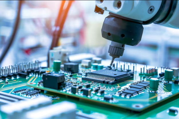
Robotic depaneling emerges as a subset, where articulated arms with end-effectors perform routing or picking tasks. These robots adapt to complex geometries via CAD data import, minimizing setup times between jobs. Electrical engineers appreciate the precision, as systems maintain tolerances that prevent trace damage or via failures. Overall, automation elevates depaneling to match Industry 4.0 standards, with inline configurations feeding directly into inspection or packaging.
Robotic Depaneling
Robotic depaneling leverages multi-axis robots equipped with routing spindles or laser heads to execute intricate cuts on tab-routed panels. The robot's vision system scans fiducials for alignment, compensating for minor panel shifts common in high-speed SMT output. This method shines for high-mix production, where frequent changeovers demand flexibility without retooling. Factories report smoother workflows as robots handle fragile boards, like those with tall components or optics, reducing handling-induced defects.
Integration of force feedback in robotic systems further limits stress, halting motion if anomalies like foreign objects are detected. Compared to fixed gantry routers, robots offer larger work envelopes for oversized panels. For electrical engineers designing boards, specifying tab routing with adequate clearances aligns perfectly with robotic capabilities, ensuring manufacturability.
SMT Line Integration
SMT line integration positions depaneling machines inline after reflow and inspection, using standardized interfaces like SMEMA for signal handshaking between conveyors. Automated systems receive baked-out panels directly, depaneling them at rates synchronized with pick-and-place output to eliminate buffers. Vision-guided loading ensures orientation, while stackers or singulators output individual boards for AOI or functional testing. This closed-loop setup enhances traceability, logging cut parameters for quality audits per ISO 9001:2015 quality management systems.
Challenges like dust management are addressed via integrated extraction and HEPA filtration, maintaining IPC-A-600K acceptability criteria for board edges and surfaces. Electrical engineers must consider panel flow when specifying V-scoring depths or tab widths to optimize integration. Successful setups achieve near-zero downtime, with quick-release fixtures for maintenance.
Automated Depaneling ROI
Automated depaneling ROI stems from labor savings, as one machine replaces multiple operators, redirecting workforce to value-added tasks like programming or troubleshooting. In high-volume factories, throughput gains compound, with systems processing panels far faster than manual methods while yielding cleaner edges that cut rework by standardizing quality. Initial capital offsets through reduced scrap and faster cycles, particularly for routing or laser types handling complex boards.
Factory analyses highlight scalability: low-volume runs may delay payback, but growth accelerates it via consistent uptime exceeding 95 percent. Integration with SMT lines amplifies ROI by balancing line speed, avoiding upstream idling. Electrical engineers evaluating ROI factor uptime, maintenance intervals, and energy use, often finding payback within 12 to 24 months in mid-sized operations.
Best Practices for Implementation
Select depaneling types matching panel design, adhering to IPC-6012E qualification specs for rigid boards to ensure post-separation performance. Implement vision systems for fiducial alignment, reducing offsets below critical tolerances. Factory best practices include regular spindle or laser calibration, dust collector maintenance, and operator training on programming interfaces. For robotic systems, simulate paths offline to verify stress-free cuts.
Edge quality inspections post-depaneling confirm compliance with IPC-A-600K, using profilometers for burr detection. Phased integration starts with offline pilots before inline deployment, monitoring cycle times against SMT takt. Sustainable practices like recyclable fixturing and energy-efficient drives align with ISO 9001:2015 process controls.
Conclusion
PCB depaneling automation revolutionizes manufacturing by enhancing efficiency, slashing labor costs, and upholding board reliability. From routing and laser systems to full robotic integration, these technologies adapt to diverse factory needs while minimizing stress on assemblies. SMT line synchronization ensures balanced production, delivering ROI through scalability and quality gains. Electrical engineers gain from standardized processes that align design with fabrication realities. Adopting these systems positions factories for competitive edge in demanding electronics markets.
FAQs
Q1: What are the main types of depaneling machines suitable for automated PCB depaneling systems?
A1: Depaneling machine types include V-scoring separators, routing mills, laser ablators, punching presses, and saws. Routing and laser excel in automation for complex shapes with low stress, integrating vision for precision. V-scoring suits straight-line high-volume via blade or guillotine. Selection depends on panel design and throughput, with routing versatile for SMT follow-on. Factory insights favor enclosed systems for dust control.
Q2: How does robotic depaneling improve efficiency in PCB production?
A2: Robotic depaneling uses articulated arms for flexible routing on tabbed panels, with vision alignment handling variations. It reduces setup for high-mix runs, minimizing stress via force sensing. Efficiency gains from continuous operation matching SMT speeds, cutting labor needs. Engineers benefit from CAD-driven paths ensuring precise outlines without custom tooling.
Q3: What factors influence automated depaneling ROI?
A3: Automated depaneling ROI factors include volume, labor rates, scrap reduction, and throughput matching SMT lines. High-volume offsets equipment costs via labor savings and uptime. Integration lowers cycle times, enhancing yield. Factories calculate based on maintenance and energy, often seeing quick payback in scaling operations.
Q4: How to integrate automated PCB depaneling systems with SMT lines?
A4: SMT line integration uses SMEMA interfaces for conveyor sync, with automated loading post-reflow. Vision ensures alignment, stackers handle output. Dust extraction maintains cleanliness per standards. Engineers verify panel specs for compatibility, piloting inline to balance takt time.
References
IPC-6012E — Qualification and Performance Specification for Rigid Printed Boards. IPC, 2017
IPC-A-600K — Acceptability of Printed Boards. IPC, 2020
ISO 9001:2015 — Quality Management Systems. ISO, 2015


