ALLPCB


1. Sterilizer control analysis
Sterilizers are important equipment for protecting human health. In developed countries, both household and commercial sterilizers are widely used.
The effectiveness of sterilization largely depends on the reliability of the control system. To address issues such as unstable control and an unfriendly human-machine interface observed at a medical equipment manufacturer, a control system was designed around the 80C196KB microcontroller to replace the original system and add some functions. Compared with the 8051 series, the 96-series provides richer on-chip resources, which simplifies the system design.
This sterilizer performs sterilization for five categories: packaged items, instruments, latex products, liquids, and others. The process is generally the same across categories, with differences handled by software. According to the operating principle shown in Figure 1, actions are controlled based on whether the inner and outer chamber temperature and pressure reach specified values.
There are four analog inputs: outer-chamber temperature TW, outer-chamber pressure PW, inner-chamber temperature TL, and inner-chamber pressure PL. There are 16 control outputs: outer-chamber steam inlet valve IW, outer-chamber steam exhaust valve OW, inner-chamber steam inlet valve IL, inner-chamber steam exhaust valve OL, vacuum valve ZK, drying air valve GZ, oil pump relay YB, vacuum pump relay ZB, solenoid hydraulic valves (high-pressure valve GF, rack valve CF, door-latch valve MF), and signal indicators (power indicator PowerL, main power indicator PowerZ, fault indicator ERR, buzzer alarm AL).

Figure 1. Operating principle
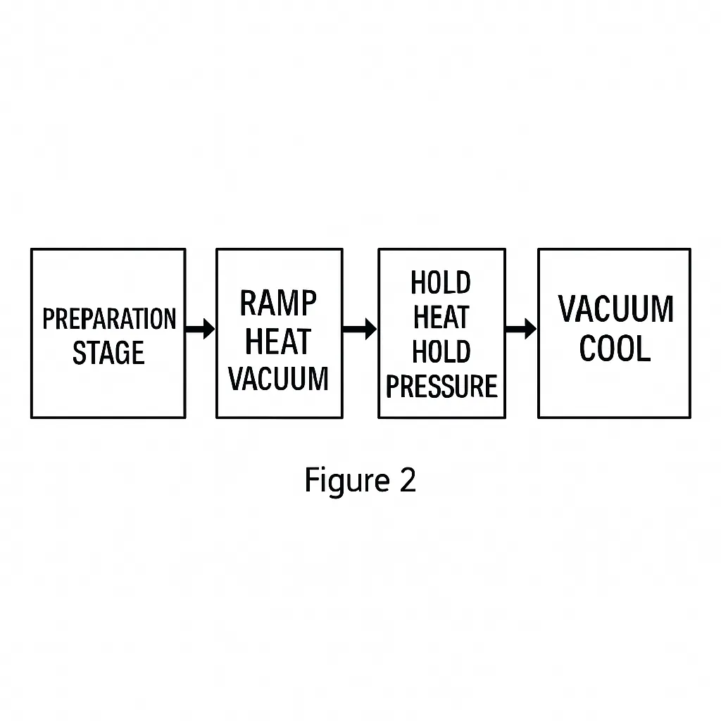
The sterilizer body is a high-pressure vessel with a jacket and a sealed door. It is equipped with a vacuum pump, vacuum valve, steam valves, control elements, and temperature and pressure sensors. The working process is illustrated in Figure 2.
2. Control system hardware structure
The hardware structure of the control system is shown in Figure 3.
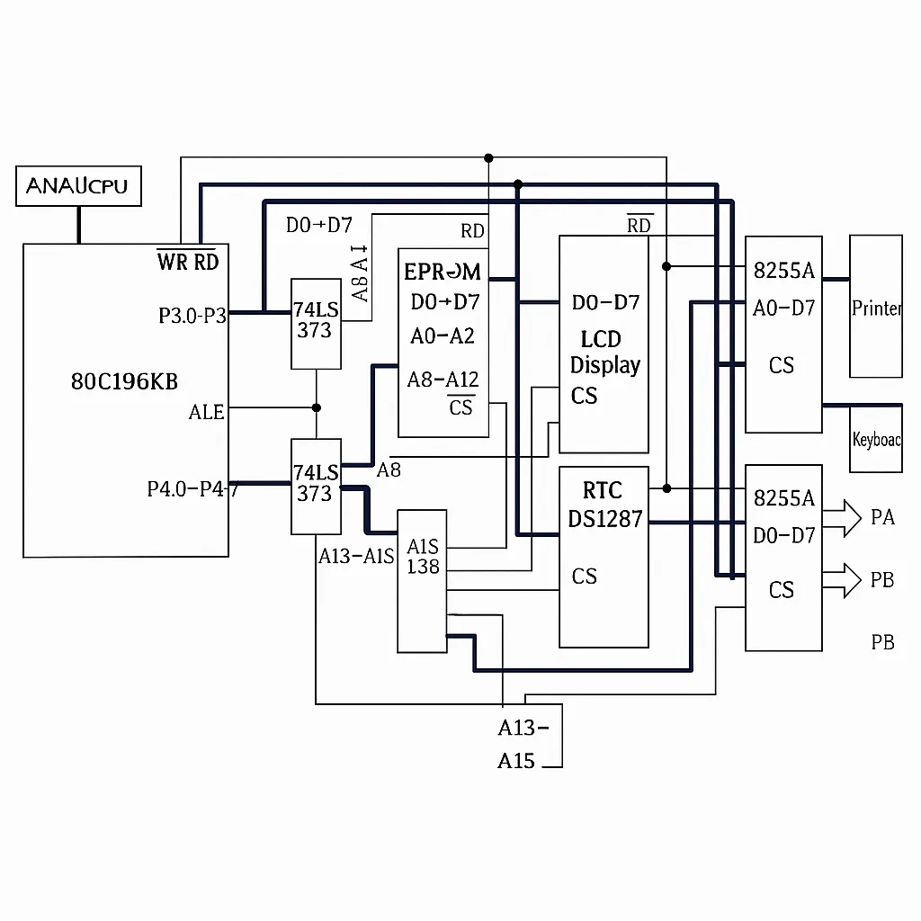
Figure 3. Control system hardware structure
The actual temperature and pressure in the sterilization chamber are measured by an integrated temperature sensor AD590JH and an integrated pressure sensor MPX5500D. The two temperature signals and two pressure signals are fed via P0.0 to P0.3 into the 80C196CKB chip. The 80C196CKB contains an 8-channel 10-bit A/D converter suitable for multi-channel data acquisition. One A/D conversion requires 88 state cycles, which is 22 us when using a 12 MHz crystal. This on-chip A/D greatly simplifies external hardware and improves circuit reliability.
Digital signals in the 80C196CKB undergo digital filtering and scaling. Processed values are displayed on the LCD and compared with setpoints to produce the deviation E and the deviation change rate EC, which are used for subsequent control. A parallel output interface 8255A implements nearly 20 switch-control outputs. Temperature control is achieved by adjusting the steam valve opening; the control signal is converted by a D/A to an analog output and amplified to drive the steam valve. The user sets sterilization temperature, time, and vacuum pulse count via the keyboard to meet various disinfection requirements.
A DS12887 parallel real-time clock module is used for timekeeping.
The human-machine interface includes a keyboard, display, and micro-printer interface. The keyboard is implemented as a soft keyboard, with key scanning, debouncing, and confirmation handled in software. An 8255A handles the hardware interface for both the keyboard and the printer. The display module uses an LCD with a built-in T6963C controller, connected directly to the CPU, to dynamically show temperature, pressure, time, and operation prompts. The printer is used to print relevant operating process parameters. The user interface is implemented in software using distributed modules rather than a single centralized module.
The system is powered from a single +5 V supply. Because signals are susceptible to interference during data acquisition, optocoupler isolation is used at signal input and output points, and shielding and resistor measures are applied to ensure system stability.
3. Software design
To ease design and maintenance, a top-down structured modular approach was used. Independent functions are implemented as subroutine modules. The main program includes initialization, sterilization type selection and related displays, parameter comparison, and actuator output control. The core tasks are temperature and pressure parameter comparison and corresponding output control. Dynamic time display is handled by Timer 1 overflow interrupt service routine. Four-channel temperature and pressure data acquisition and dynamic display are handled by the A/D conversion-complete interrupt service routine. Because the display routine is relatively large, running it in an interrupt handler keeps the background program concise and improves software reliability. The program flow is shown in Figure 4.
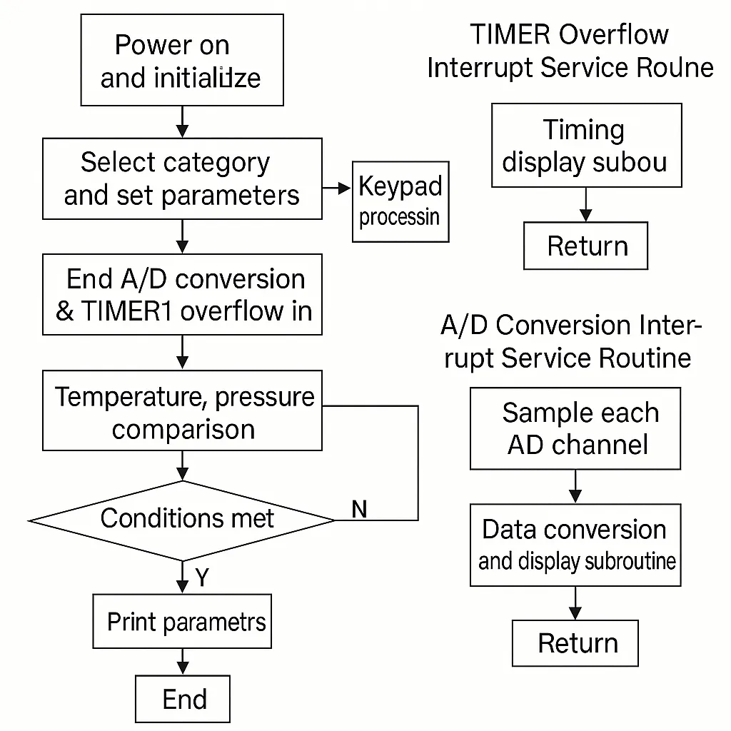
Figure 4. Program flowchart
The basic runtime process is: after initialization, A/D conversion is started to sample temperature and pressure signals. After processing, these data are compared with user-set operating parameters, and actuator actions are determined to keep the operating parameters within required process ranges.
The system software is implemented entirely in assembly language for high execution efficiency and reliable operation. Detailed code is omitted here.
4. Conclusion
This is a practical embedded control system centered on the 80C196KB. It offers complete functions with a relatively simple design. Field applications show stable operation and reliable sterilization control. Compared with PLC-based sterilizer control systems with similar functionality, this design is lower cost, has a user-friendly interface, and is easier to operate.