ALLPCB


If you're new to the world of printed circuit board (PCB) design and manufacturing, you might be wondering, "What is IPC-2581, and why does it matter?" Simply put, IPC-2581 is a modern, open standard for transferring PCB design data between designers and manufacturers. It streamlines the process, reduces errors, and ensures all necessary information is conveyed in a single, unified format. In this comprehensive guide, we’ll dive into an IPC-2581 tutorial for beginners, provide an IPC-2581 introduction, explain understanding IPC-2581 data format, and explore what is IPC-2581 standard. Whether you're an engineer or a hobbyist, this post will help you grasp the essentials and see why this standard is transforming the industry.
What Is IPC-2581 Standard? A Beginner-Friendly Overview
IPC-2581 is a vendor-neutral, open standard developed by the Institute of Printed Circuits (IPC) to facilitate the exchange of PCB design and manufacturing data. Unlike older formats like Gerber files, which often require multiple files to convey different aspects of a design (such as layers, drill data, and netlists), IPC-2581 combines all this information into a single, intelligent file. Introduced in 2004, it has evolved into a powerful tool for ensuring seamless communication between design software and manufacturing systems.
Why is this important for beginners? When you're designing a PCB, the data you create needs to be accurately interpreted by the manufacturer to produce the board. Errors in data transfer can lead to costly mistakes, delays, or even defective products. IPC-2581 minimizes these risks by providing a standardized format that includes everything from artwork and drill data to bill of materials (BOM) and assembly instructions.
Why IPC-2581 Matters in PCB Design and Manufacturing
For those just starting in PCB design, understanding why IPC-2581 is gaining traction is crucial. Traditional formats like Gerber have been around for decades, but they come with limitations. For instance, Gerber files are essentially image-based and lack the ability to carry detailed metadata or intelligent data like netlist information. This often requires additional files or manual intervention, increasing the chance of errors.
IPC-2581, on the other hand, is a "smart" format. It not only includes visual data but also embeds critical details like component placement, test pad information, and even design variants. This means manufacturers can extract all the information they need from one file, reducing miscommunication. For beginners, this translates to fewer headaches when sending designs for production and a smoother workflow overall.
Here are some key benefits of IPC-2581:
- Unified Data: Combines design, fabrication, and assembly data in one file, eliminating the need for multiple formats.
- Error Reduction: Minimizes manual data handling, reducing the risk of mistakes during data transfer.
- Bidirectional Communication: Supports feedback loops between designers and manufacturers, allowing for quick corrections.
- Vendor-Neutral: Works across different software and systems, ensuring compatibility regardless of the tools you use.
IPC-2581 Introduction: How It Works in Simple Terms
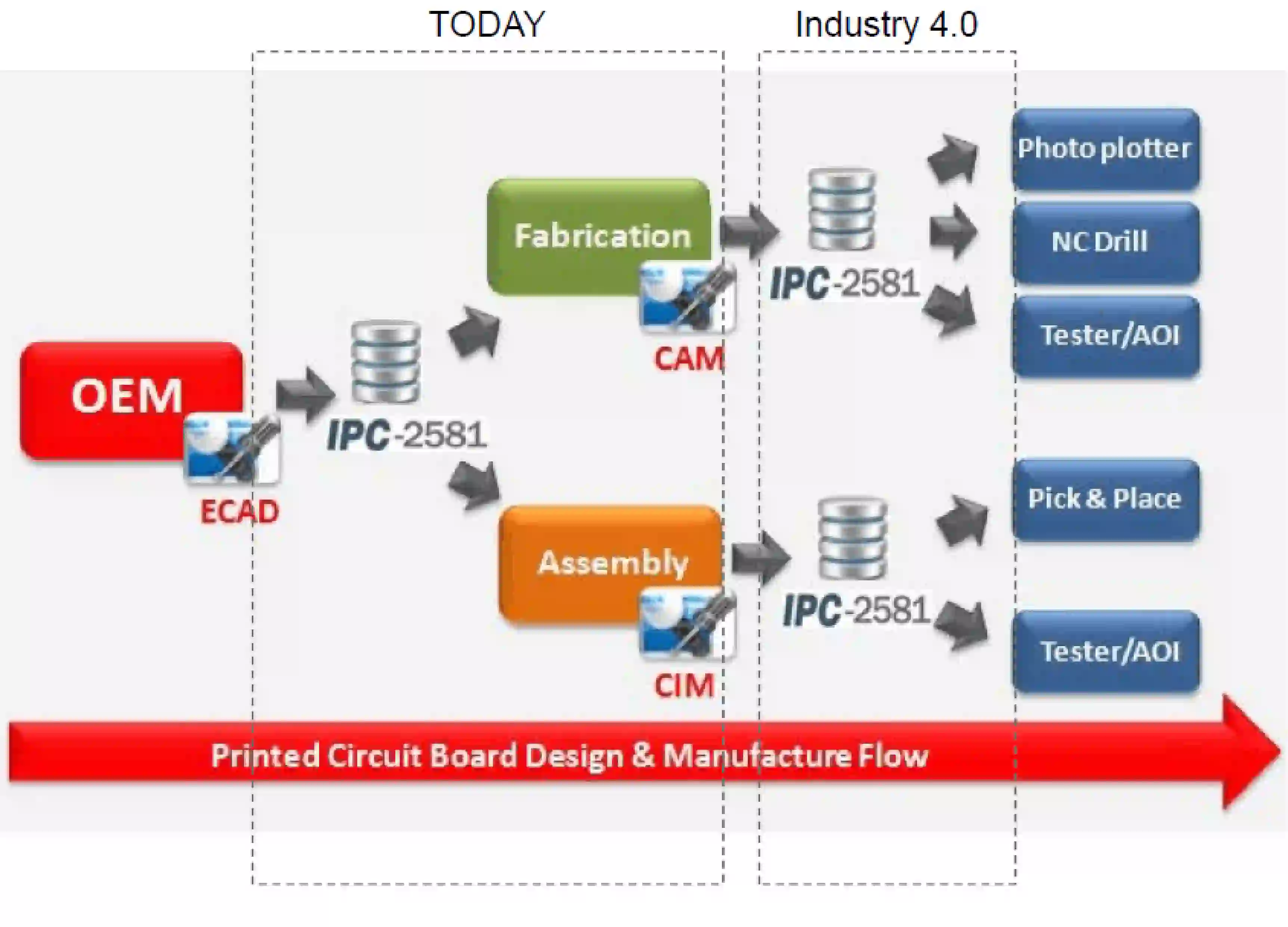
Let’s break down the basics of IPC-2581 for beginners. At its core, IPC-2581 is a digital product model exchange (DPMX) standard. This means it acts as a bridge between the design phase (where you create your PCB layout) and the manufacturing phase (where the board is fabricated and assembled). The format is based on XML, a widely used language for structuring data, which makes it both human-readable and machine-readable.
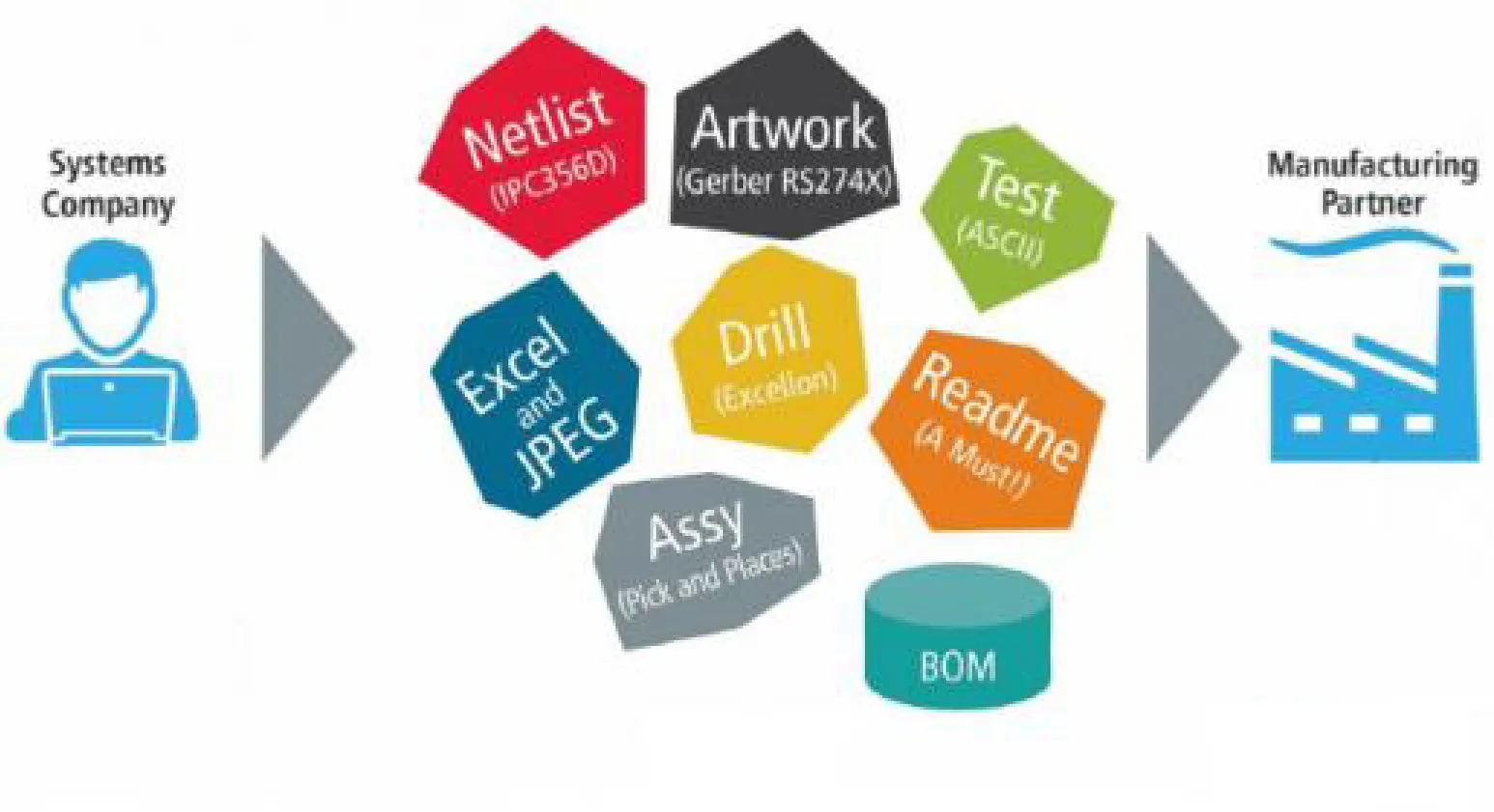
Imagine you’ve designed a PCB with multiple layers, components, and specific drilling requirements. With older methods, you’d export separate files for each layer, a netlist file for connections, and additional documents for assembly instructions. With IPC-2581, all of this information is packaged into a single file. When a manufacturer receives this file, their systems can automatically interpret the data, ensuring that every detail—from copper traces to component placement—is accurately reproduced.
For a beginner, the takeaway is simple: IPC-2581 saves time and reduces confusion by standardizing how data is shared. It’s like sending a complete blueprint of your design in one neat package instead of scattered pieces of a puzzle.
Understanding IPC-2581 Data Format: A Deep Dive for Beginners
Now that you have a basic grasp of what IPC-2581 is, let’s explore understanding IPC-2581 data format. While the technical details can be complex, we’ll keep it beginner-friendly. The IPC-2581 format is structured to include several key categories of data, ensuring that every aspect of a PCB design is covered. Here’s what’s typically included in an IPC-2581 file:
- Design Data: This includes the layout of copper traces, pads, and vias across all layers of the PCB. It’s the visual representation of your board’s structure.
- Netlist Information: This defines the electrical connections between components, ensuring the manufacturer understands how everything is wired.
- Bill of Materials (BOM): A list of all components needed for assembly, including part numbers and quantities.
- Drill Data: Specifications for holes and vias, including sizes and locations, critical for fabrication.
- Assembly Instructions: Details on component placement and orientation for the assembly process.
- Test Data: Information on test points and procedures to verify the board’s functionality after production.
Because IPC-2581 uses an XML-based structure, it’s highly organized and flexible. For instance, if a manufacturer needs to adjust a specific layer due to production constraints, they can easily locate and modify that data within the file. For beginners, this means you don’t need to worry about sending incomplete or mismatched files—everything is in one place.
One notable feature is its support for bidirectional data exchange. This means manufacturers can send feedback or updated files back to designers in the same format, making collaboration smoother. For example, if a drilling specification needs adjustment due to equipment limitations, the manufacturer can update the IPC-2581 file and return it for review.
IPC-2581 Tutorial for Beginners: How to Get Started
If you’re ready to start using IPC-2581 in your PCB projects, this IPC-2581 tutorial for beginners will guide you through the initial steps. While the exact process depends on the design software you’re using, the general workflow remains consistent.
Step 1: Check Software Compatibility
Ensure that your PCB design software supports IPC-2581 export. Many modern tools have built-in support for generating IPC-2581 files. Look for an export option in the fabrication or output settings of your software.
Step 2: Prepare Your Design
Complete your PCB layout, including all layers, components, and annotations. Double-check that your netlist, BOM, and drill data are accurate, as these will be included in the IPC-2581 file.
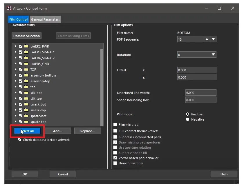
Step 3: Export the IPC-2581 File
In your software, select the option to export fabrication data in IPC-2581 format. This will generate a single file (typically with a .cvg extension) containing all the necessary data. Some software might allow you to customize what data is included—ensure all relevant categories (design, assembly, etc.) are selected.
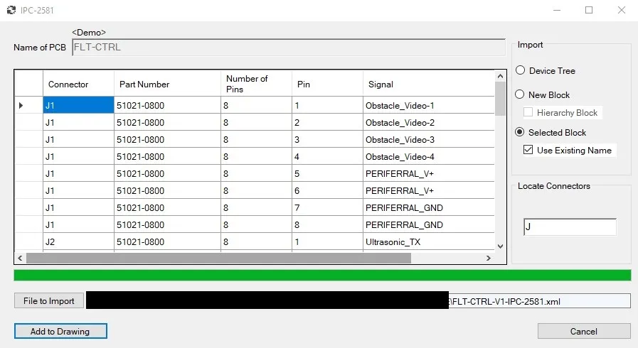
Step 4: Verify the File
Before sending the file to a manufacturer, use a viewer tool or validator to confirm that the IPC-2581 file contains all the required information. Some tools provide previews of the design data to ensure nothing is missing.
Step 5: Send to Manufacturer
Share the IPC-2581 file with your manufacturing partner. Since it’s a standardized format, most manufacturers familiar with modern workflows will be able to process it without issues. Confirm with them that they accept IPC-2581 files to avoid any compatibility hiccups.
Challenges and Considerations for Beginners Using IPC-2581
While IPC-2581 offers numerous advantages, beginners should be aware of a few challenges. First, not all manufacturers have fully adopted this standard yet. Some smaller or traditional facilities may still prefer older formats like Gerber due to familiarity or outdated systems. If this is the case, you might need to provide alternative files alongside IPC-2581.
Second, there’s a learning curve if you’re transitioning from older formats. While the concept of a single file is straightforward, understanding how to configure export settings or troubleshoot issues with the file might take time. Thankfully, resources like forums, tutorials, and software documentation can help.
Lastly, ensure that your design software is up to date. Older versions might not support IPC-2581 or may have limited functionality, leading to incomplete data exports. Always check for updates or patches that enhance compatibility with this standard.
Comparing IPC-2581 to Other PCB Data Formats
For beginners, it’s helpful to understand how IPC-2581 stacks up against other common formats. Here’s a quick comparison:
- Gerber Files: Image-based, requiring separate files for each layer and aspect of the design. Lacks intelligent data and is prone to errors during manual handling.
- ODB++: A more advanced format that includes intelligent data, but it’s proprietary and not as widely supported as IPC-2581.
- IPC-2581: Combines intelligent data with an open, vendor-neutral structure. Supports bidirectional communication and reduces errors with a single-file approach.
For a beginner, starting with IPC-2581 (if supported by your tools and manufacturer) can save time and reduce the likelihood of mistakes compared to juggling multiple Gerber files.
The Future of IPC-2581 in PCB Design
As the electronics industry continues to evolve, IPC-2581 is poised to become the go-to standard for PCB data transfer. Its ability to handle complex designs, support bidirectional communication, and reduce errors aligns with the industry’s push for automation and efficiency. For beginners, adopting IPC-2581 early in your career can give you a head start in understanding modern workflows and preparing for future advancements.
Industry experts predict that as more manufacturers and software developers adopt IPC-2581, older formats will gradually phase out. This shift is already underway, with many leading design tools incorporating robust support for the standard. By learning IPC-2581 now, you’re future-proofing your skills and ensuring compatibility with cutting-edge production methods.
Conclusion: Start Using IPC-2581 for Seamless PCB Data Transfer
In summary, IPC-2581 is a game-changer for anyone involved in PCB design and manufacturing. This IPC-2581 introduction and IPC-2581 tutorial for beginners has covered the essentials of what is IPC-2581 standard and provided a clear path to understanding IPC-2581 data format. By adopting this open, intelligent standard, you can streamline data transfer, minimize errors, and collaborate more effectively with manufacturers.
Whether you’re designing a simple single-layer board or a complex multi-layer system, IPC-2581 ensures that your vision is accurately translated into a finished product. Take the time to explore this standard in your design software, verify compatibility with your manufacturing partners, and embrace the future of PCB data exchange. With IPC-2581, seamless communication between design and production is within your reach.