ALLPCB


Circuit principle
Currently, infusion requires staff to monitor the drip chamber so they can notify clinicians when the fluid is nearly exhausted. This increases caregiver workload, especially at night after surgery when multiple bag changes are needed.
This article describes a prototype infusion monitor. A small probe is clamped around the infusion drip chamber. As the liquid level in the drip chamber falls, the capacitance formed by two copper plates inside the probe decreases. When the level drops below a preset threshold, the monitor generates an audible alarm to notify staff. Laboratory tests showed good sensitivity and accuracy.
This design uses a non-contact sampling method: capacitive sensing. Two copper plates are attached to the inner surface of a transparent acrylic frame to form the level sensor, as shown in Figure 1. During infusion, the drip chamber is positioned between the two copper plates. The capacitance depends on the dielectric between the plates; liquid has a higher permittivity than air, so the capacitance varies with liquid level. The liquid level signal is obtained by measuring the capacitance between the two copper plates.
The acrylic housing is formed from glued acrylic sheets. The front is open so the drip chamber level is visible. The capacitance between the two copper plates is proportional to the liquid level: as the level falls, capacitance decreases and the measured voltage falls. After amplification and comparison, if the voltage is below the set threshold the speaker issues an alert tone similar to an ambulance siren.
The automatic infusion monitor circuit is shown in Figure 2. Inverter gates IC1, IC2 and IC3 with resistors R1, R2 and capacitor C1 form an oscillator that generates an AC signal. C3 is the capacitance formed by the two copper plates of the level sensor. The oscillator AC signal is coupled through C2 and C3 to diode VD1 for rectification, producing a DC signal.

The capacitance C3 varies with the liquid level, so the rectified DC amplitude represents the drip chamber level. Operational amplifier IC4 with resistors R4 and R5 forms a non-inverting amplifier. Because the monitor operates at low supply voltage and C3 is small, the DC signal is very weak.
IC4 amplifies the signal by roughly two times and feeds it to IC5. IC5, together with potentiometer RP and resistor R6, is configured as a comparator. Potentiometer RP sets the trip voltage (alarm threshold). The threshold is set to approximately 80% of full-scale voltage, where full-scale is the voltage produced when the liquid level equals the upper edge of the copper plates.
When the liquid level falls, the DC signal drops. If it falls below the preset threshold, IC5 outputs a high level. The signal is inverted by IC6 and IC7 (these stages improve alarm stability; experiments showed the alarm threshold was unstable without them), which drives transistor VT1 into conduction. IC8 is a four-tone music IC configured to produce an ambulance siren melody (see Figure 3). When VT1 conducts it connects the negative rail of IC8 to ground, enabling the music IC.
IC8 drives the speaker BL to produce the siren sound. Changing R9 adjusts the speaker volume. VD3 is a zener diode; together with R7 and C5 it forms a regulator so the circuit can operate down to about 4.1 V.
Component selection
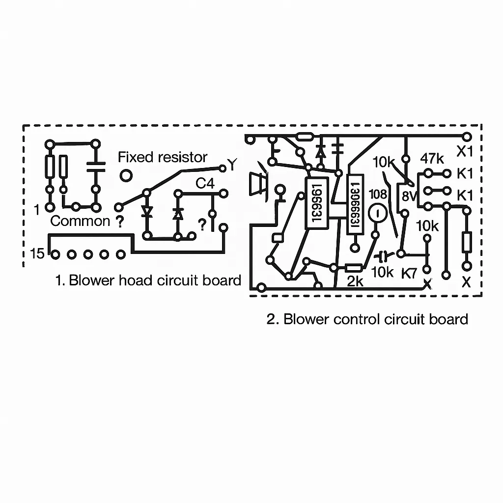
The circuit inside the dashed box in Figure 2 is assembled on a small PCB of about 50 mm × 22 mm. The PCB layout is shown in Figure 4 and is fixed to the back of the drip chamber sensor housing. The probe and the small PCB together form the drip chamber probe. Other components are installed in a small enclosure that functions as the monitor control box. The probe and control box can be connected with a cable up to about 1.2 m.
The monitor uses two TC4069UBP IC packages: IC1, IC2 and IC3 share one chip, while IC6 and IC7 use the other.
The probe output is very weak and susceptible to interference. To extend the probe-to-control-box cable while minimizing interference, wires X1, X2 and X3 should use two-core shielded cable; the shield must be grounded and a three-pin connector used. The speaker should be an ultra-thin internal-magnet type under 10 mm thick.
Connector X is an earphone jack. Plugging in earphones allows only staff to hear the alarm, avoiding disturbance to the patient. Capacitors C1 and C2 must be mica capacitors. If the leads to C3 exceed 40 mm, use shielded cable for C3.
Adjustment and testing
Because the probe sensor is an acrylic frame, dimensional tolerances make it difficult to manufacture identical sensors; the full-scale voltage of each sensor may differ. The following example describes a practical calibration method used in testing.
With the liquid level aligned with the top edge of the copper plates, measure the voltage at test point K1. If K1 is 1.000 V, adjust potentiometer RP so that point K2 reads 0.800 V. Slowly lower the drip chamber level; when the level falls to approximately 80% of the original level, the alarm should activate.
If alarm outputs from individual infusion monitors are routed to a central nurse station, staff can promptly identify which bed requires a bag change.