ALLPCB


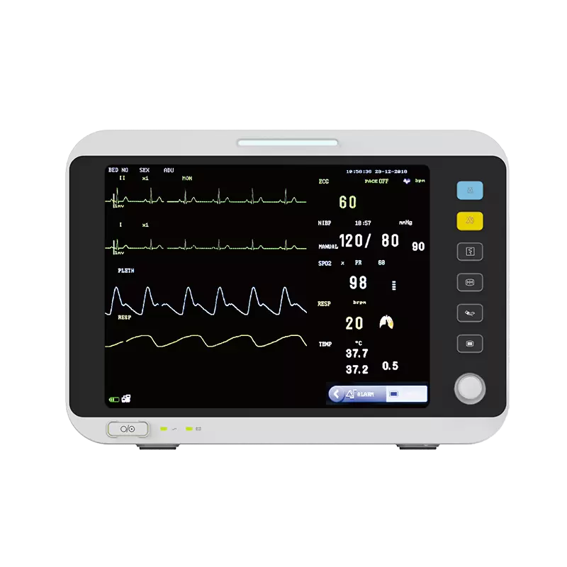
Portable ECG Monitor: Front-End Amplifier
2.4 Isolation between digital and analog circuits
Portable monitors combine digital and analog circuits. During layout, interference between analog and digital sections must be considered. Digital circuits operate at high frequencies while analog circuits are highly sensitive. High-frequency signal traces should be routed as far as possible from sensitive analog components. Although the PCB has a single external ground node, digital and analog grounds are typically separated inside the PCB and only tied at the external interface. Ferrite beads, also called EMI/RFI suppressors, provide effective suppression of high-frequency interference and can be used to block conducted interference on wiring and cables. In this design, a 6.8LH ferrite bead is used to isolate the analog and digital power rails.
2.5 Component placement and PCB design
A PCB contains multiple circuit types: small-signal analog, high-speed digital, and high-frequency GPRS or RF signals. To avoid coupling between these sections and the resulting interference, separate placement for each circuit type is a basic PCB design principle. Sections should be kept at adequate distances and routed separately.
Power routing, including VDD and VSS, is critical for system immunity. VDD and VSS planes should be made as large as possible to reduce electromagnetic emissions from strong electromagnetic energy and to ensure a low-impedance return path for high-frequency signals.
2.6 Shielding for analog circuitry
Weak ECG signals are buried in various electromagnetic fields that induce interference in the body. Those induced voltages couple through the body and lead wires via capacitance or inductance to the interference sources. High-frequency signals such as GPRS can significantly affect the small analog signals presented to the A/D converter.
Therefore, in addition to separating analog and digital sections on the PCB, the analog circuitry should be covered with a shield enclosure.
3 Software anti-interference design
When random interference mixes with the input signal, analog filters can remove unwanted components to improve signal quality. However, analog filters are difficult to implement at low and very low frequencies; digital filters do not have these limitations. Digital filters offer high precision, reliability, and stability, and are widely used to mitigate errors caused by random interference. Digital filters can be implemented in two ways: a frequency-domain method using FFT to perform discrete Fourier transforms and filter according to desired frequency characteristics, and a time-domain method that performs difference operations on sampled data. The time-domain method is simple and practical for real applications. Digital filters are classified by impulse response width into finite impulse response (FIR) and infinite impulse response (IIR) filters. IIR filters have infinite memory and fewer computation terms, and for the same order provide higher precision. To ensure filtering quality while improving speed, an IIR filter is used in this design.
3.1 Low-pass filter design
To remove frequencies above the ECG band, the sampling frequency is set to fs = 200 Hz, so T = 5 ms. Based on the ECG frequency range, the cutoff frequency is chosen as fc = 99 Hz. From low-pass filter design parameters, the passband ripple is rp = 0.1 dB, the stopband attenuation is rs = 60 dB, and the order is n = 4.
3.2 Notch filter design
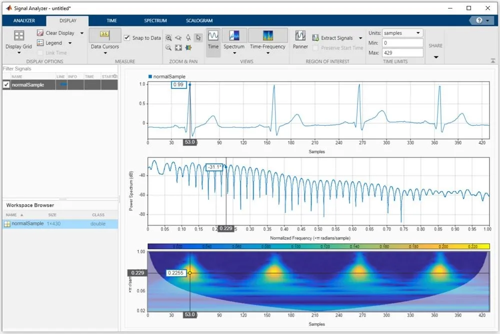
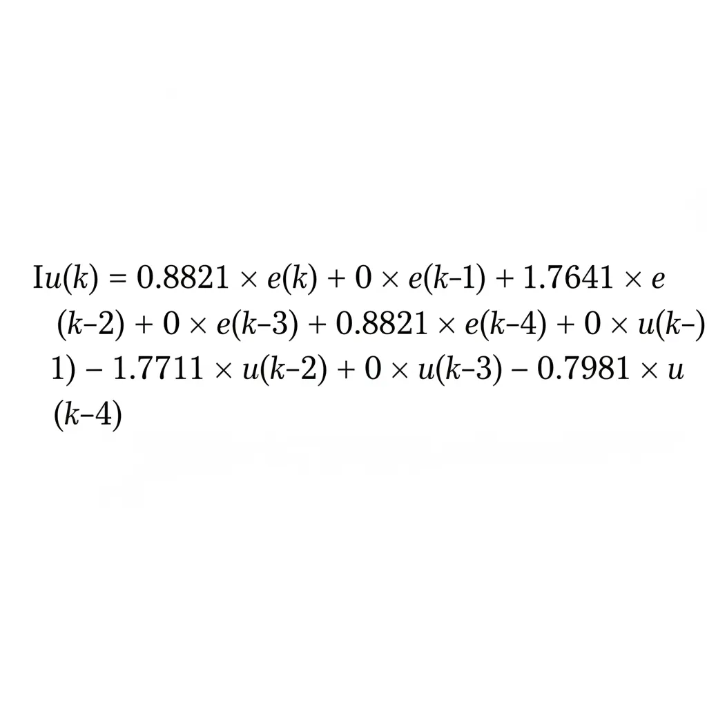
Experiments show that relying on an analog notch filter alone to remove 50 Hz mains interference is insufficient. Therefore a digital filter is also used to remove mains interference. Sampling frequency is fs = 200 Hz, so T = 5 ms. An elliptic-function filter is used. Design parameters: passband edges wp1 = 45, wp2 = 55; stopband edges ws1 = 49.8, ws2 = 50.2. Passband ripple rp = 0.1 dB, stopband attenuation rs = 60 dB. Matlab design yields the following algorithm formulas and responses:
Dialysis system flow and control (excerpt)
Two identical chambers are separated by a composite high-elasticity diaphragm. Under hydraulic pressure the diaphragm flexes left and right. Each chamber has inlet and outlet ports connected to three-way solenoid valves that control dialysate flow in and out. During operation, when solenoid valve V1 connects the lower port, water driven by the drainage pump enters chamber A and the diaphragm flexes left, increasing A's volume. Simultaneously solenoid valve V2 connects its upper and lower ports, forcing water out of chamber B through the delivery sensor. The delivery sensor monitors dialysate flow in the volume chamber; when the chamber is detected empty, it issues a control signal to switch the states of V1 and V2. When switched, water enters chamber B, the diaphragm flexes right, and chamber A is emptied. The delivery sensor detects flow again and the cycle repeats. With fixed chamber volume, counting valve switches via the delivery sensor yields precise delivered dialysate volume.
Dialysate from the delivery sensor flows into an average flow control unit composed of a flow control valve and a flow feedback valve. The flow control valve is a three-way controllable valve; outlet flow equals inlet flow minus feedback flow. Controlling feedback flow magnitude controls the average dialysate flow. The feedback valve is controlled by a DC motor, with an accuracy of ±5 ml/min; average dialysate flow is continuously adjustable between 400 and 600 ml/min. When the A-solution monitor detects conductivity and temperature within set ranges, bypass three-way valve V14 connects left and right ports, valve V15 opens, and dialysate enters the dialyzer. Waste fluid after ion exchange exits the dialyzer, passes through the filter, V15, pressure sensor, and enters the blood leak detector. The blood leak detector is a red-cell detector that prevents dialysate from entering blood if the dialyzer membrane ruptures, ensuring treatment safety.
Sensitivity is adjustable between 200 and 1000 ppm, so mixing as little as 0.2 to 1 ml of blood per liter of dialysate can be detected and alarmed. Dialysate pressure sensors monitor pressure to prevent membrane rupture from excessive pressure and to protect treatment efficacy.
Waste fluid leaving the blood leak detector is drawn into a degassing chamber by a negative-pressure pump; air accumulates at the top of the sealed degassing chamber. A float switch opens solenoid valve V8 to vent air, maintaining discharge chamber flow accuracy. Waste fluid is then discharged through the drain volume chamber, drain sensor, pressure offset device (POD), and heat exchanger. The negative-pressure pump is a DC variable-speed pump that controls pump speed based on the configured patient ultrafiltration rate (0 to 5.99 L/h). Control voltage ranges from 8 V to 21 V, and pump inlet pressure (i.e., dialysate pressure) ranges from 70 mmHg to -400 mmHg. The drain volume chamber and drain sensor operate like the delivery chamber and sensor and can precisely measure drained waste volume. Patient net ultrafiltration equals drained volume minus delivered volume. Precise control of pump speed enables control of ultrafiltration rate and total ultrafiltration, with accuracy ±30 ml/h. POD is connected via solenoid valve V7 to the patient's venous pressure port to reduce TMP fluctuations from venous pressure changes and improve ultrafiltration accuracy. The heat exchanger uses the temperature of expelled waste fluid to preheat incoming reverse-osmosis water.
In "disinfection" and "acid wash" modes the main water path remains unchanged, but bypass three-way valve V14 connects the upper right port and valve V15 closes so water does not enter the dialyzer. A and B solution suction tubes are placed into their respective wash chambers; solenoid valves V9, V10, and V11 open. Disinfectant and acid wash solution flow under A- and B-solution pumps through V9, V10, V11 and AB wash chambers into the main water path to disinfect and acid-wash the water system.
In "cleaning" mode the main water path is the same as in "disinfection" mode; suction tubes for A solution, B solution, disinfectant, and acid wash solution are placed into their wash chambers, valves V9, V10, V11 open, and A and B pumps reverse. Water flows from the main line through AB wash chambers and various valves and wash chambers and is discharged through the outlet, simultaneously cleaning the entire water circuit, suction tubes, and wash chambers.
The JMS S DS-20 hemodialysis machine's water system differs from other brands (for example Fresenius, Nikkiso) in that it eliminates the ultrafiltration pump: the negative-pressure pump performs both negative-pressure degassing and ultrafiltration, combined with inlet/outlet volume chambers and POD to precisely control ultrafiltration. This simplifies the water path and reduces machine cost while retaining the same functions.
4 Conclusion
As a portable monitor, simplicity of hardware and small size are inherent requirements. This article proposes a single-polarity power approach for the front-end amplifier and discusses ECG interference reduction strategies. The focus has been on hardware anti-interference solutions; software anti-interference is also important for meeting portable device constraints and will be detailed in a later article on ECG signal preprocessing.