 ALLPCB


Introduction
Printed circuit boards form the backbone of modern electronics, carrying signals and power through intricate networks of traces and components. Ensuring their functionality requires rigorous testing at various stages, from bare board inspection to fully assembled prototypes. Electrical engineers rely on specialized equipment to verify continuity, signal integrity, and performance under operational conditions. A well-equipped PCB testing station prevents field failures and optimizes design iterations. This article outlines the essential PCB testing equipment list, focusing on tools that deliver precise diagnostics. Mastering these instruments aligns production with industry benchmarks for reliability.
Why PCB Testing Equipment Matters for Electrical Engineers
PCB testing equipment enables engineers to detect defects early, reducing rework costs and accelerating time-to-market. Faults like open circuits, shorts, or signal distortion can compromise system performance, leading to cascading failures in complex assemblies. Standards such as IPC-A-610 define acceptability criteria for electronic assemblies, emphasizing electrical verification alongside visual checks. Comprehensive testing confirms compliance with design specifications and environmental stresses. In high-volume manufacturing, automated and manual tools together ensure consistency across batches. For electrical engineers, selecting the right equipment translates theoretical designs into robust, field-ready products.
Core Principles of PCB Electrical Testing
Electrical testing on PCBs involves measuring parameters like resistance, voltage, capacitance, and waveform characteristics to validate interconnects and components. Continuity tests confirm trace connectivity, while insulation resistance checks prevent leakage paths. Dynamic testing simulates operational signals to reveal timing issues or noise susceptibility. Tools must offer sufficient bandwidth and resolution for high-speed signals common in modern designs. Factory-driven protocols integrate these measurements with standards like IPC-6012 for rigid board qualification. Understanding measurement principles ensures accurate interpretation and troubleshooting.
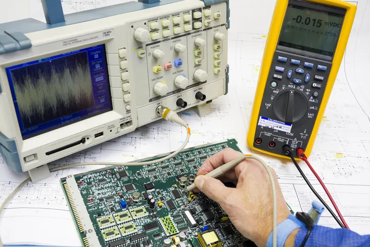
Multimeter for PCB Testing
A multimeter stands as the foundational tool in any PCB testing equipment list, offering versatile measurements of voltage, current, resistance, and continuity. Engineers use it to probe traces for opens or shorts, verifying solder joint integrity without powering the board. Diode testing mode assesses component polarity and forward voltage drop, critical for debugging power rails. In resistance mode, it detects high-impedance faults that might escape visual inspection. Auto-ranging features simplify fieldwork, while high-resolution models handle low-value measurements precisely. For assembled boards, current limiting protects sensitive components during in-circuit checks.
Multimeters excel in passive testing, providing quick diagnostics before advancing to active signal analysis. Engineers often pair beeper functions with visual cues for efficient continuity sweeps across dense layouts. Capacitance and frequency modes extend utility to component verification. Regular calibration maintains accuracy, aligning with quality control protocols. This tool's portability makes it indispensable for bench and field repairs alike.
Oscilloscope for PCB Testing
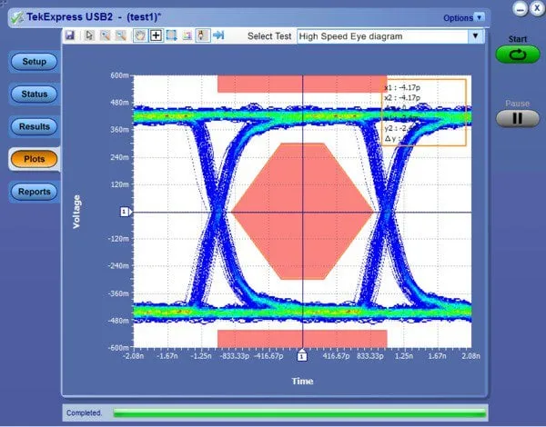
Oscilloscopes capture and display voltage waveforms over time, making them essential for dynamic PCB analysis. Electrical engineers employ them to inspect signal rise times, overshoot, and jitter on data lines. Triggering capabilities isolate anomalies like glitches or ringing in clock signals. Bandwidth selection matches the highest frequencies in the design, ensuring faithful reproduction. Probes with adjustable compensation minimize loading effects on circuits. Math functions enable FFT analysis for frequency domain insights, revealing harmonic distortions.
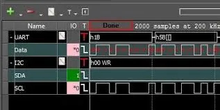
In PCB troubleshooting, oscilloscopes differentiate analog noise from digital crosstalk. Differential probing suits high-voltage or balanced signals common in power electronics. Persistence modes visualize intermittent faults elusive to single-shot captures. Serial decoding protocols like I2C or SPI accelerate bus debugging. Integration with logic analyzers expands multi-domain testing. Proper grounding prevents measurement artifacts, upholding test validity.
Function Generator for PCB Testing
Function generators produce customizable waveforms to stimulate PCB circuits under test, simulating real-world inputs. Engineers generate sine, square, or pulse signals to evaluate filter responses or amplifier gains. Arbitrary waveform capability replicates complex stimuli for protocol compliance checks. Amplitude and offset controls mimic power supply variations, stressing voltage regulators. Frequency sweeps characterize bandwidth limits in RF sections. Synchronization outputs coordinate with oscilloscopes for end-to-end verification.
This equipment proves vital for functional validation before integration. Modulation options test demodulator circuits in communication modules. Output impedance matching prevents signal distortion. Burst modes simulate packetized data flows. Low-distortion outputs ensure clean references for noise floor assessments. In design phases, it facilitates loop tuning in feedback systems.
Logic Analyzer for PCB Testing
Logic analyzers capture multiple digital signals simultaneously, ideal for debugging state machines and bus interactions. With dozens of channels, they timestamp transitions to reveal timing violations or protocol errors. Engineers configure thresholds per signal family, accommodating mixed 3.3V and 5V logic. Protocol analyzers decode UART, SPI, or CAN traffic, correlating events across buses. Deep memory buffers handle long acquisition windows for infrequent glitches. State reconstruction maps address and data for microprocessor emulation.
In complex PCBs, logic analyzers outperform oscilloscopes for parallel signal correlation. Compression algorithms extend effective memory depth. External clocking synchronizes with device under test clocks. Setup/hold qualifiers filter spurious edges. Exporting traces to simulation tools closes the debug loop. This tool scales from prototypes to production debug fixtures.
Additional Key Tools in the PCB Testing Equipment List
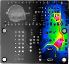
Beyond core instruments, a DC power supply provides stable voltages to power prototypes safely, with current limiting to avert damage. LCR meters measure inductance, capacitance, and resistance at specific frequencies, verifying passives in-circuit. Thermal cameras detect hot spots from shorts or poor thermal design. Flying probe testers automate bare board continuity and isolation for high-mix production. Spectrum analyzers profile RF emissions and interference susceptibility. Together, these form a complete arsenal for multifaceted diagnostics.
Engineers select tools based on board complexity and test objectives. Benchtop units offer precision, while USB variants enhance portability. Fixture design optimizes probe access, reducing handling errors. Software integration streamlines data logging and reporting. Calibration traceability supports audit-ready processes.
Best Practices for Implementing PCB Testing Protocols
Standardize test sequences starting with visual and continuity checks, progressing to powered functional tests. Document golden waveforms and thresholds for repeatable pass/fail criteria. Ground planes properly to isolate measurements. Use shielded cables for high-frequency probes. Cross-verify findings across tools, like oscilloscope signals with logic analyzer states. Incorporate environmental chambers for stressed testing per JEDEC guidelines.
Training ensures consistent technique application. Automated scripting accelerates regression testing. Data analytics trend defect patterns for process improvements. Collaborate with design teams on test point placement early. These practices elevate quality control to factory standards.
Troubleshooting Common PCB Failures with Testing Equipment
Intermittent power issues often trace to marginal solder joints, confirmed by multimeter resistance fluctuations under vibration. Signal integrity problems manifest as waveform distortions, pinpointed by oscilloscope eye patterns. Digital hangs correlate with logic analyzer state timeouts. Component drift appears in LCR deviations. Systematic probing isolates root causes efficiently. Post-fix retesting validates repairs.
Case insights from production lines highlight equipment synergy. A logic analyzer revealed bus contention missed by scopes alone. Function generators exposed resonance peaks in power filters. These examples underscore proactive testing value.
Conclusion
The PCB testing equipment list centers on multimeters, oscilloscopes, function generators, and logic analyzers, augmented by supporting tools for thorough validation. Electrical engineers leverage these for precise fault isolation and performance assurance. Adhering to standards like IPC-A-610 and IPC-6012 fortifies reliability. Investing in quality instruments pays dividends in reduced escapes and faster iterations. Equipped properly, teams deliver PCBs that excel in demanding applications. Prioritize calibration and training to maximize return on this essential infrastructure.
FAQs
Q1: What makes a multimeter essential in the PCB testing equipment list?
A1: Multimeters provide fundamental checks for continuity, resistance, voltage, and current on PCBs, detecting basic faults like opens and shorts quickly. They support in-circuit component verification without full power-up, minimizing risks. High accuracy aids voltage drop analysis in power distribution networks. Paired with other tools, they form the starting point for systematic debugging. This versatility suits bench and production environments alike.
Q2: How does an oscilloscope enhance PCB testing for signal integrity?
A2: Oscilloscopes visualize time-domain waveforms, revealing rise times, overshoot, and noise on PCB traces critical for high-speed designs. Trigger functions isolate rare events, while FFT exposes frequency content. Proper probing ensures minimal circuit loading. Engineers use them to validate timing budgets against specs. Integration with generators simulates loads accurately.
Q3: When should electrical engineers use a function generator for PCB testing?
A3: Function generators apply controlled stimuli to PCBs, testing responses in amplifiers, filters, and digital inputs. Waveform variety simulates operational conditions, uncovering bandwidth limits or distortions. Sweeps characterize frequency responses precisely. Synchronization with scopes measures phase shifts. They prove invaluable for analog and mixed-signal validation.
Q4: Why include a logic analyzer in the PCB testing equipment list?
A4: Logic analyzers handle multi-channel digital captures, decoding protocols and timing on buses like SPI or I2C. Deep memory tracks long sequences for glitch detection. Threshold adjustments suit varied logic levels. They excel where scopes lack channel count. Protocol insights accelerate embedded system debug.
References
IPC-A-610H — Acceptability of Electronic Assemblies. IPC, 2017
IPC-6012E — Qualification and Performance Specification for Rigid Printed Boards. IPC, 2017
J-STD-001H — Requirements for Soldered Electrical and Electronic Assemblies. IPC, 2018


