 ALLPCB


Introduction
Solder joints serve as the critical electrical and mechanical connections in electronic assemblies, enduring repeated thermal stresses throughout their lifecycle. Thermal cycling, which simulates real-world temperature fluctuations, reveals vulnerabilities in these joints that can lead to premature failures. Engineers focused on reliability must understand solder joint thermal cycling testing to predict and enhance performance under harsh conditions. This process not only identifies fatigue mechanisms but also guides design optimizations for longer service life. By mastering thermal cycling effects on solder joints, teams can develop robust assemblies that meet demanding operational requirements. The following sections delve into the principles, challenges, and strategies for optimization.
Understanding Solder Joint Thermal Cycling Testing
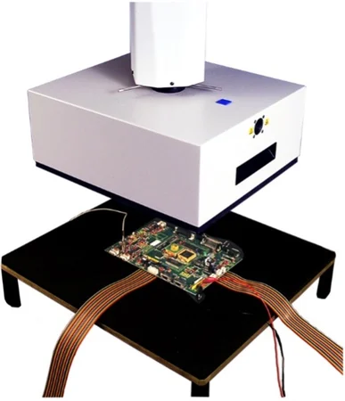
Solder joint thermal cycling testing involves subjecting assemblies to controlled temperature excursions to accelerate aging and assess durability. This method replicates environmental stresses like power-on/off cycles or outdoor exposure, where temperatures swing between extremes. Standards such as IPC-9701 outline specific test conditions to characterize fatigue lifetimes of surface mount attachments. Testing typically uses daisy-chain boards to monitor electrical continuity, detecting failures through resistance increases. Engineers select cycle profiles based on end-use environments, ensuring results correlate with field performance. This testing remains essential for qualifying components in automotive, aerospace, and consumer electronics.
The procedure demands precise chamber control, with dwells at high and low temperatures to allow full thermal stabilization. Ramp rates influence strain rates, mimicking operational realities without inducing shock. Failure analysis post-testing involves cross-sectioning joints to observe crack propagation. Data from multiple samples enable statistical analysis, often using Weibull distributions for characteristic life predictions. Integrating this testing early in design prevents costly redesigns later. Ultimately, it provides quantifiable metrics for comparing material and process variations.
Thermal Cycling Effects on Solder Joints
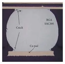
Thermal cycling effects on solder joints stem primarily from coefficient of thermal expansion (CTE) mismatches between joined materials. Printed boards expand more than silicon dies or ceramic packages during heating, imposing shear strains on the ductile solder. Repeated cycles cause low-cycle fatigue, where plastic deformation accumulates microcracks at stress concentration points. These cracks often initiate at the solder-to-pad interface or intermetallic layers, growing inward over time. Grain coarsening and recrystallization further degrade joint integrity, reducing load-bearing capacity.
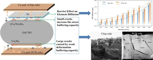
Microstructural evolution plays a key role, as thermal exposure promotes intermetallic compound growth that embrittles boundaries. Viscoplastic behavior of the solder alloy governs damage accumulation, with creep contributing at elevated temperatures. Finite element analysis helps quantify these strains, highlighting high-risk joint geometries. Underfill materials can redistribute stresses, extending cycles to failure. Monitoring via strain gauges or high-speed imaging during tests reveals dynamic responses. Understanding these mechanisms allows engineers to anticipate failure modes accurately.
Environmental factors amplify effects, such as humidity accelerating corrosion in cracks or vibration compounding fatigue. Solder composition influences resistance; lead-free alloys like SAC305 exhibit different creep rates compared to tin-lead. Board thickness and layout affect global warpage, altering local strains. Post-reflow cooling rates impact initial microstructure, setting the stage for cycling endurance. Comprehensive characterization demands combining testing with modeling for holistic insights.
Solder Joint Fatigue in Thermal Cycling
Solder joint fatigue thermal cycling represents a dominant failure mode, characterized by progressive crack growth under cyclic shear loading. Fatigue life correlates inversely with strain amplitude, following models like Coffin-Manson relations adapted for solder. Crack paths follow paths of maximum shear, often along board or component interfaces. Propagation accelerates as effective joint area diminishes, leading to open circuits.
Testing per JEDEC JESD22-A104 standardizes conditions, ensuring comparability across suppliers. Cycles to first failure provide baseline reliability, while characteristic life accounts for population variability. Factors like standoff height modulate strain; taller joints accommodate more deformation. Pad finish types influence intermetallic formation, affecting fatigue resistance. Engineers optimize by balancing fillet geometry for stress relief without voids.
Advanced diagnostics, including acoustic microscopy, detect subsurface damage early. Vibration-assisted cycling reveals synergies with mechanical loads. Alloy dopants refine microstructures, mitigating recrystallization. Process controls during assembly minimize defects that serve as crack initiators. By addressing these, designs achieve margins exceeding field requirements.
Best Practices for Optimizing Reliability
Optimizing solder joint reliability begins with material selection to minimize CTE differentials. Low-CTE laminates or silicon carriers reduce baseline strains, extending fatigue life. Underfilling BGA or flip-chip packages encapsulates joints, converting shear to compression. Engineers calculate optimal underfill properties via simulation to avoid fillet cracking.
Pad design per J-STD-001 guidelines ensures uniform solder volume distribution. Larger pads or dog-bone shapes enhance compliance, while NSMD (non-solder mask defined) pads promote barrel-shaped joints for better fatigue resistance. Reflow profiling controls peak temperatures and times, preserving alloy properties. Post-assembly inspections verify fillet quality and voiding levels.
Finite element modeling predicts strain energy density, guiding iterative improvements. Virtual thermal cycling shortens design cycles, correlating with physical tests. Stenciling precision achieves consistent paste deposits, minimizing defects. Bake-out processes precondition boards, simulating aging without damage. Layer stackups influence warpage; symmetric builds maintain planarity.
Reliability qualification integrates sequential stresses: thermal cycling followed by vibration or humidity. Data-driven acceleration factors extrapolate lab results to service life. Supplier audits verify process capabilities against specs. Field return analysis refines models, closing the loop.
Troubleshooting Common Issues
Engineers encounter inconsistent test results from chamber nonuniformity or fixture-induced stresses. Verify temperature profiles with thermocouples at multiple board locations. Daisy-chain resistance spikes signal early failures; X-ray confirms crack locations. Excessive warpage warps joints prematurely; thinner cores or low-modulus fillers help.
Voiding reduces effective area, accelerating fatigue. Optimize stencil apertures and reflow to under 25% voids in critical joints. Intermetallic overgrowth from slow cooling embrittles; tighten ramp-down rates. Multi-component boards demand zoned heating for uniform melting.
Conclusion
Mastering solder joint thermal cycling testing unlocks reliable electronics design. Thermal cycling effects on solder joints highlight CTE-driven fatigue as the key challenge. Solder joint fatigue thermal cycling demands proactive strategies: precise materials, geometry, and processes. Standards like IPC-9701 and JEDEC JESD22-A104 provide proven frameworks. Implementing best practices ensures assemblies withstand real-world demands. Engineers prioritizing these elements deliver products with superior longevity.
FAQs
Q1: What is solder joint thermal cycling testing and why is it essential?
A1: Solder joint thermal cycling testing exposes assemblies to repeated temperature changes to simulate operational stresses and predict fatigue life. It identifies weaknesses from CTE mismatches early, preventing field failures. Following IPC-9701 protocols ensures standardized, repeatable results for qualification. This testing guides optimizations in design and materials for enhanced reliability. Electric engineers rely on it to validate performance margins.
Q2: How do thermal cycling effects on solder joints lead to failure?
A2: Thermal cycling effects on solder joints arise from differential expansion, causing shear strains and low-cycle fatigue. Cracks start at interfaces and propagate, reducing electrical continuity. Microstructural changes like grain growth exacerbate damage. Underfill and pad design mitigate these by redistributing loads. Testing per JEDEC JESD22-A104 quantifies cycles to failure for risk assessment.
Q3: What best practices improve solder joint fatigue thermal cycling performance?
A3: To combat solder joint fatigue thermal cycling, select low-CTE materials and apply underfill for stress relief. Optimize pad geometry for compliant fillets and control reflow for minimal voids. Use FEA simulations to predict strains and iterate designs. Adhere to J-STD-001 for assembly quality. These steps extend characteristic life significantly in demanding applications.
Q4: How can engineers predict solder joint reliability under thermal cycling?
A4: Engineers predict reliability using accelerated testing per IPC-9701, analyzing Weibull plots from daisy-chain data. Coffin-Manson models extrapolate strains to cycles. Combine with FEA for geometry-specific insights. Correlate lab data with field conditions via acceleration factors. Regular failure analysis refines predictions for ongoing improvements.
References
IPC-9701B — Performance Test Methods and Qualification Requirements for Surface Mount Solder Attachments. IPC, 2011
JEDEC JESD22-A104F — Temperature Cycling. JEDEC, 2020
J-STD-001H — Requirements for Soldered Electrical and Electronic Assemblies. IPC/JEDEC, 2020


