 ALLPCB


Introduction
In PCB assembly processes, ensuring the integrity of solder joints and hidden components is critical for reliable electronics. X-ray machines provide non-destructive inspection capabilities that reveal defects invisible to optical methods. Electric engineers face increasing demands for high-density assemblies like BGAs and QFNs, where traditional visual checks fall short. Selecting the appropriate X-ray machine involves balancing specifications, budget, and operational needs. This guide breaks down key factors to help you make an informed decision. By focusing on practical aspects, you can enhance quality control without unnecessary complexity.
What Is a PCB Assembly X-Ray Machine and Why It Matters
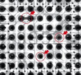
A PCB assembly X-ray machine uses X-ray radiation to penetrate assemblies and produce images of internal structures. It detects issues such as voids, cracks, bridging, and misalignments in solder joints, particularly under dense packages. In high-volume manufacturing, these tools integrate into inline or offline inspection workflows to meet stringent quality requirements. According to IPC-A-610 acceptability criteria, many defects like insufficient solder volume or head-in-pillow issues require subsurface analysis that X-ray excels at providing. Without proper inspection, failures in the field can lead to costly recalls and reliability problems. For electric engineers, investing in the right system directly impacts yield rates and compliance with industry benchmarks.
The relevance grows with miniaturization trends in consumer electronics and automotive sectors. X-ray inspection verifies assembly processes against J-STD-001 requirements for soldered joints, ensuring mechanical and electrical performance. Engineers troubleshooting intermittent failures often rely on these machines to pinpoint root causes quickly. Overall, they reduce scrap rates and support process optimization over time.
Key X-Ray Machine Specifications to Consider
When evaluating X-ray machine specifications, start with resolution and magnification, as they determine defect detection limits. Microfocus tubes offer resolutions down to a few microns, essential for fine-pitch components below 0.3mm. Detector type, such as flat-panel or line-scan, affects image quality and speed; amorphous silicon detectors provide high contrast for low-contrast defects like micro-voids. Field of view (FOV) and geometry settings allow inspection of various board sizes without repositioning. Tube voltage and current settings, typically 40-160kV, must penetrate thick assemblies while minimizing blur. Software features for automated defect recognition (ADR) streamline analysis for high-throughput environments.
Next, consider inspection speed and automation compatibility. Tilt and rotate axes enable oblique views, crucial for shadowed areas in stacked components. Integration with conveyor systems supports inline use, reducing handling time. Data export formats should align with statistical process control (SPC) tools for tracking trends. Power consumption and footprint matter for facility planning, especially in cleanroom setups. Prioritize specs that match your assembly complexity to avoid over- or under-specification.
2D vs 3D X-Ray: Understanding the Differences
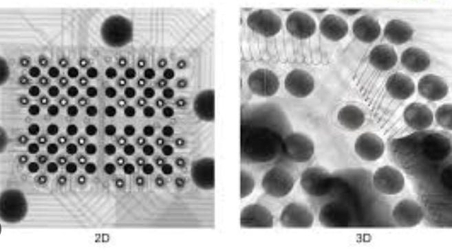
2D X-ray systems project a single-plane image, suitable for quick checks on simple assemblies. They excel in detecting large voids or gross misalignments but struggle with overlapping features, leading to false calls. Image quality depends on angle selection, and interpretation requires operator skill. For low-to-medium density boards, 2D suffices and offers faster cycle times.
In contrast, 3D X-ray uses computed tomography (CT) or digital laminography to reconstruct volumetric data. This eliminates overlap, providing slice views for precise depth measurements in multilayer stacks. Resolution in Z-axis allows quantification of void percentages, aligning with detailed failure analysis. However, 3D systems demand longer scan times and higher computational power.
Choosing between 2D vs 3D X-ray hinges on your application. 2D works for prototype verification or spot checks, while 3D is ideal for high-reliability sectors like aerospace. Hybrid systems combine both for flexibility. Evaluate based on defect types prevalent in your process.
Factors Influencing X-Ray Machine Price Comparison
X-ray machine price comparison starts with system capability; basic 2D units cost less than advanced 3D models due to simpler hardware. Tube type significantly impacts price: sealed tubes are affordable but have shorter lifespans, while open tubes offer longevity at a premium. Detector resolution and size drive costs, as higher pixel counts enhance detail but increase expense.
Automation level affects pricing; manual systems are entry-level, whereas fully automated inline machines include robotics and software suites. Footprint and shielding requirements add to the total, especially for high-power units. Ongoing costs like software licenses and service contracts should factor into long-term value.
Budget allocation considers throughput needs: high-volume lines justify pricier systems with ROI through reduced escapes. Entry-level options suit R&D, while production demands robust builds. Compare total ownership costs, including installation and training, for accurate assessment.
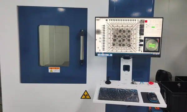
Essential X-Ray Machine Safety Features
X-ray machine safety features protect operators from radiation exposure, a primary concern in daily use. Interlock systems halt emission if doors open or panels shift, preventing accidental exposure. Lead-lined enclosures and collimators minimize scatter radiation to below regulatory limits.
Dose monitoring with alarms and personal dosimeters ensures compliance. Emergency stop buttons and key controls restrict access. Ventilation systems handle ozone from high-voltage components. Modern units include real-time dose readouts and automatic shutoff after idle periods.
For electric engineers, verify features like fail-safe software and shielding verification tests. User training on safe practices complements hardware. These elements enable safe integration into workflows without compromising productivity.
Best Practices for X-Ray Machine Maintenance
X-ray machine maintenance extends tube life and maintains image fidelity. Schedule daily visual checks for leaks or damage, followed by calibration using standard phantoms. Tube hours tracking triggers replacements before failure, typically after 10,000 hours depending on usage.
Weekly software updates and detector cleaning prevent artifacts. Annual professional servicing verifies geometry and radiation output per manufacturer guidelines. Log all maintenance for traceability and warranty compliance.
Troubleshoot common issues like blurry images by checking focal spot size or alignment. Overheating points to cooling system faults; address promptly. Train staff on error codes for quick resolution. Consistent upkeep minimizes downtime and ensures consistent defect detection.
Troubleshooting Insights for PCB X-Ray Inspection
Electric engineers often encounter challenges like artifact interpretation in dense assemblies. Start by optimizing kV and mA for material thickness to improve contrast. For BGA void analysis, use multiple angles in 2D or slices in 3D to confirm findings.
False positives from board warpage require fixturing; secure panels flat during scans. Software glitches manifest as grid lines; reboot and recalibrate detectors. Correlate X-ray data with cross-sections for validation against IPC-A-610 class levels. Document setups for repeatable results.
Conclusion
Choosing the right PCB assembly X-ray machine demands careful review of specifications, 2D vs 3D capabilities, pricing factors, safety, and maintenance needs. Prioritize alignment with your process complexity and volume for optimal ROI. Robust systems enhance quality control, reduce escapes, and support standards compliance. Electric engineers benefit from hands-on evaluation and vendor demos focused on real workflows. Invest thoughtfully to safeguard assembly reliability long-term.
FAQs
Q1: What are the most important X-ray machine specifications for PCB BGA inspection?
A1: Key specifications include microfocus tube resolution under 5 microns, high magnification up to 200x, and flat-panel detectors for contrast. FOV should cover typical panel sizes, with tilt axes for oblique views. Automated measurement tools aid void quantification. These ensure detection of fillet issues per J-STD-001, balancing speed and accuracy in production.
Q2: How does 2D vs 3D X-ray impact PCB assembly quality control?
A2: 2D X-ray offers fast, cost-effective planar imaging for basic defects but misses depth info in overlaps. 3D provides volumetric slices for precise analysis in complex stacks, ideal for high-reliability apps. Choose 2D for volume checks, 3D for failure analysis. Transition based on defect escape rates to optimize workflows.
Q3: What factors should I consider in X-ray machine price comparison?
A3: Compare tube type, detector quality, automation, and 2D/3D features, as they dictate upfront and lifecycle costs. Factor in service contracts and throughput matching. Entry 2D systems suit labs; advanced 3D for inline use. Total cost of ownership guides value over lowest bid.
Q4: How to maintain an X-ray machine for reliable PCB inspections?
A4: Perform daily calibrations, weekly cleanings, and tube hour monitoring. Annual servicing checks shielding and geometry. Troubleshoot artifacts via settings tweaks. Consistent logs support warranty and process stability, minimizing downtime in assembly lines.
References
IPC-A-610H — Acceptability of Electronic Assemblies. IPC, 2017
J-STD-001H — Requirements for Soldered Electrical and Electronic Assemblies. IPC, 2018


