 ALLPCB


If you're working on printed circuit board (PCB) diagnostics and need a reliable tool to measure electrical properties, an LCR meter is your go-to device. So, what is an LCR meter? It’s a specialized instrument used to measure inductance (L), capacitance (C), and resistance (R) of electronic components. For PCB diagnostics, it helps test components like capacitors, inductors, and resistors, ensuring they function correctly by providing precise readings of impedance and other parameters. In this guide, we’ll dive deep into how an LCR meter works, why it’s essential for testing PCB components, and step-by-step instructions on using it effectively for inductance measurement, capacitance measurement, resistance measurement, and impedance measurement.
Understanding the Basics of an LCR Meter
An LCR meter is a versatile piece of test equipment designed to evaluate the fundamental electrical properties of components on a PCB. Whether you're troubleshooting a faulty board or verifying component values during assembly, this tool is indispensable for engineers and technicians. Let’s break down what it measures:
- Inductance (L): This is the ability of a component, like an inductor, to store energy in a magnetic field. It’s measured in Henries (H).
- Capacitance (C): This measures a component’s ability to store electric charge, typically in capacitors, and is expressed in Farads (F).
- Resistance (R): This indicates how much a component resists the flow of electric current, measured in Ohms (Ω).
Additionally, advanced LCR meters can calculate impedance, which combines resistance and reactance (from inductance and capacitance) to give a complete picture of a component’s behavior under alternating current (AC) conditions. Impedance is crucial for understanding how components interact in a circuit, especially at different frequencies, and is often measured in Ohms (Ω) as well.
Why Use an LCR Meter for PCB Diagnostics?
PCBs are the backbone of modern electronics, packed with tiny components that must work together seamlessly. A single faulty capacitor or inductor can cause an entire board to malfunction. Using an LCR meter for testing PCB components offers several benefits:
- Accuracy: LCR meters provide precise measurements, often with an accuracy of ±0.1% for resistance and ±0.2% for inductance and capacitance, depending on the model.
- Speed: They allow quick testing of multiple components without needing to desolder them in many cases, saving valuable time during diagnostics.
- Versatility: Beyond basic L, C, and R values, many meters measure secondary parameters like equivalent series resistance (ESR) of capacitors (typically in the range of 0.01 Ω to 100 Ω for common capacitors) or the quality factor (Q) of inductors.
For instance, if a capacitor on a PCB shows a capacitance value far below its rated 10 μF (microfarads), or if its ESR is unusually high (e.g., above 1 Ω when it should be under 0.1 Ω), you can identify it as defective before it causes further issues. This makes LCR meters essential for both quality control during PCB assembly and troubleshooting after production.
How Does an LCR Meter Work?
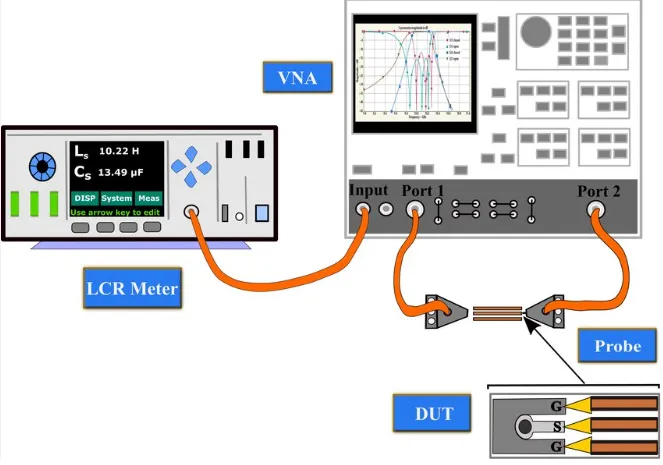
At its core, an LCR meter operates by applying an AC signal to the component under test, often at a selectable frequency ranging from 100 Hz to 100 kHz or higher. The meter then measures the voltage across and the current through the component. By analyzing the relationship between voltage and current, including their phase difference, the meter calculates the component’s inductance, capacitance, resistance, or impedance.
For example, when testing an inductor at 1 kHz, the meter might detect an inductance of 10 mH (millihenries) and a small resistance component due to the coil’s wire. This dual measurement helps assess whether the inductor meets its specifications for a particular circuit design.
Understanding the frequency setting is critical because component behavior changes with frequency. Capacitors, for instance, have lower impedance at higher frequencies, while inductors show higher impedance. Selecting the right test frequency (often specified in component datasheets, such as 1 kHz for general-purpose capacitors) ensures accurate results.
Step-by-Step Guide to Using an LCR Meter for PCB Diagnostics
Now that we’ve covered the basics, let’s walk through the practical steps of using an LCR meter for testing PCB components. Whether you're focusing on inductance measurement, capacitance measurement, resistance measurement, or impedance measurement, the process is straightforward if you follow these guidelines.
Step 1: Prepare Your Equipment and Workspace
Before starting, ensure you have the following:
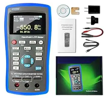
- An LCR meter (handheld or benchtop, depending on your needs).
- Test leads or probes compatible with your meter.
- The PCB or individual components you want to test.
- Component datasheets for reference values (e.g., rated capacitance of 100 nF or inductance of 220 μH).
Set up in a clean, static-free environment to avoid damaging sensitive components. If testing components on a PCB, power off the board and discharge any capacitors to prevent false readings or safety hazards.
Step 2: Calibrate the LCR Meter
Calibration ensures accurate measurements. Most LCR meters have an “open” and “short” calibration mode:
- Open Calibration: Disconnect the test leads and select the open calibration option. This accounts for stray capacitance in the leads.
- Short Calibration: Connect the test leads together and perform short calibration to eliminate lead resistance.
Calibration should be done before each testing session or when switching between different test frequencies (e.g., from 120 Hz to 10 kHz).
Step 3: Select the Measurement Mode and Frequency
Choose the parameter you want to measure—inductance (L), capacitance (C), resistance (R), or impedance (Z). Then, set the test frequency based on the component’s typical operating conditions. For example:
- For general-purpose capacitors, use 1 kHz.
- For audio inductors, 100 Hz might be more appropriate.
- For high-frequency components in RF circuits, select 100 kHz or higher if your meter supports it.
Some meters automatically select the mode by detecting the component type, but manual selection often yields better control.
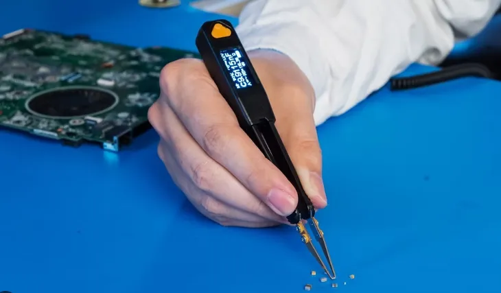
Step 4: Connect the Component to the LCR Meter
Attach the test leads to the component. For components already soldered onto a PCB, use fine-tip probes to contact the component leads directly. Ensure a secure connection to avoid erratic readings. If testing a standalone component, insert it into the meter’s test slots or clip the leads onto its terminals.
Note: For in-circuit testing, nearby components might interfere with readings due to parallel or series effects. If results seem off (e.g., a capacitor reading 50 nF instead of the expected 100 nF), consider desoldering the component for isolated testing.
Step 5: Take and Analyze Measurements
Once connected, the LCR meter will display the primary value (e.g., capacitance of 47 μF) and sometimes secondary parameters like ESR (0.05 Ω) or dissipation factor (D). Compare these readings to the component’s rated values from its datasheet. Significant deviations indicate a potential issue:
- A resistor reading 1.2 kΩ instead of 1 kΩ might be out of tolerance.
- An inductor showing 5 mH instead of 10 mH could be damaged or incorrectly specified.
For impedance measurement, note both the magnitude (e.g., 500 Ω) and phase angle if your meter provides it. This helps in understanding how the component behaves in an AC circuit.
Step 6: Record and Troubleshoot
Document your measurements for each component tested, especially if diagnosing a larger PCB. If a component fails to meet specifications, mark it for replacement. For instance, a capacitor with an ESR of 2 Ω when it should be under 0.1 Ω is likely causing circuit noise or instability and should be swapped out.
Best Practices for Accurate LCR Measurements
To get the most reliable results when using an LCR meter for PCB diagnostics, keep these tips in mind:
- Use the Correct Test Frequency: As mentioned earlier, frequency impacts readings. A mismatch (e.g., testing a 1 μF capacitor at 100 kHz instead of 1 kHz) can lead to inaccurate capacitance values.
- Minimize Lead Length: Long test leads introduce parasitic inductance and capacitance, skewing results. Keep leads as short as possible, especially at higher frequencies.
- Avoid In-Circuit Interference: If other components on the PCB affect readings, isolate the component under test by lifting one lead or fully desoldering it.
- Check Temperature Effects: Component values can drift with temperature. Test at room temperature (around 25°C) unless specified otherwise in the datasheet.
Common Applications of LCR Meters in PCB Work
LCR meters are used in various stages of PCB development and maintenance. Here are some key scenarios where they shine:
- Component Verification: Before soldering components onto a PCB, confirm their values match the design specifications. For example, ensure a 100 pF capacitor isn’t actually 120 pF, which could affect timing circuits.
- Troubleshooting Failures: Identify failed components on a malfunctioning PCB. A capacitor with zero capacitance or an open-circuit reading is a clear sign of failure.
- Quality Control: During mass production, test random samples from component batches to catch manufacturing defects early.
- Filter Design Testing: In circuits with LC filters, measure inductance and capacitance to ensure the filter operates at the correct frequency (e.g., a cutoff frequency of 10 kHz as designed).
Reated Reading: PCB Batch Production: Mastering Quality Control for Zero Defects
Limitations of LCR Meters in PCB Diagnostics
While LCR meters are powerful, they’re not without limitations. Understanding these helps set realistic expectations:
- In-Circuit Testing Challenges: As noted, nearby components can skew results, especially in densely populated PCBs.
- Frequency Range Limits: Some meters only support up to 100 kHz, which might not suffice for high-frequency RF components operating in the MHz or GHz range.
- Unable to Test Active Components: LCR meters are designed for passive components like resistors, capacitors, and inductors. They can’t evaluate transistors or ICs.
Related Reading: SMD Active Components: A Beginner's Guide to Surface Mount Design
For complex diagnostics, you might need to pair an LCR meter with other tools like oscilloscopes or multimeters to get a full picture of PCB health.
Choosing the Right LCR Meter for Your Needs
Not all LCR meters are created equal. When selecting one for PCB diagnostics, consider these factors:
- Frequency Range: Ensure the meter covers the frequencies relevant to your components (e.g., 100 Hz to 1 MHz for most PCB work).
- Accuracy: Look for models with high precision, such as ±0.05% basic accuracy for critical applications.
- Form Factor: Handheld meters are portable and great for fieldwork, while benchtop models often offer more features and higher accuracy for lab use.
- Additional Features: Some meters include ESR, Q factor, and dissipation factor measurements, which are useful for detailed diagnostics.
Conclusion: Mastering PCB Diagnostics with an LCR Meter
An LCR meter is an essential tool for anyone involved in PCB diagnostics, offering precise measurements of inductance, capacitance, resistance, and impedance. By following the steps outlined in this guide, you can confidently use an LCR meter for testing PCB components, ensuring your boards function as intended. From verifying component values during assembly to troubleshooting faults in existing circuits, the ability to perform accurate inductance measurement, capacitance measurement, and resistance measurement is a game-changer.
Invest time in understanding your LCR meter’s features and limitations, and always adhere to best practices for reliable results. With this knowledge, you’ll be well-equipped to tackle any PCB diagnostic challenge that comes your way, enhancing both efficiency and quality in your electronic projects.


