 ALLPCB


Elevator control PCBs (Printed Circuit Boards) are the heart of modern elevator systems, managing everything from motor control to safety mechanisms. When these boards malfunction, elevators can stop working, leading to costly downtime and safety concerns. If you're a technician searching for effective ways to handle elevator PCB repair or elevator control PCB troubleshooting, this guide is for you. We'll walk you through the essentials of identifying faults, using tools like a multimeter for PCB testing, and performing repairs with precision.
In this comprehensive blog post, we'll dive deep into practical techniques for elevator PCB fault finding, step-by-step testing methods, and tips for ensuring long-term reliability. Whether you're a seasoned professional or a technician looking to expand your skills, this guide offers actionable insights to keep elevators running smoothly.
What Are Elevator Control PCBs and Why Do They Matter?
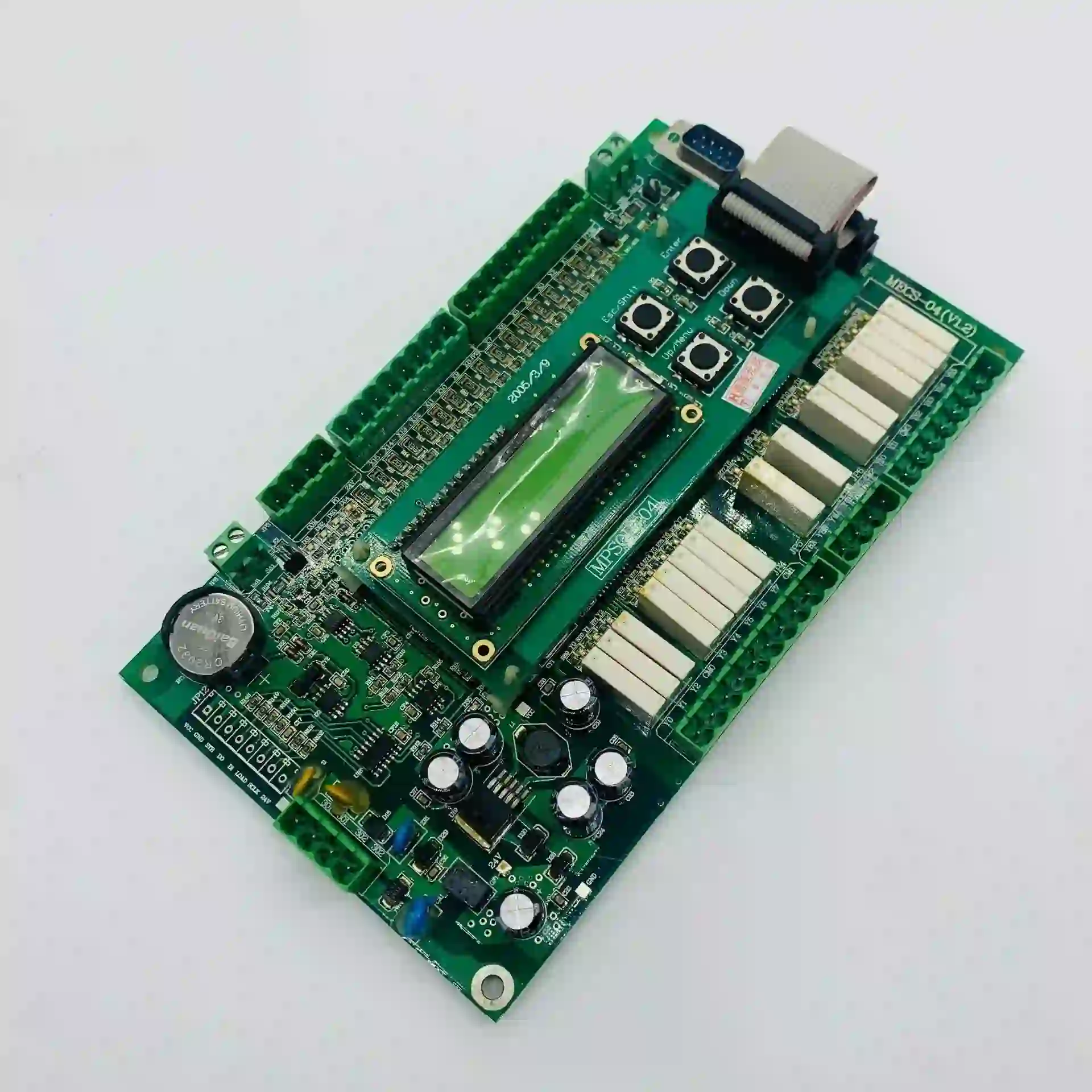
Elevator control PCBs are electronic boards that act as the central nervous system of an elevator. They process signals from buttons, sensors, and safety devices, ensuring the elevator moves safely and efficiently between floors. A single fault in the PCB can cause issues like erratic movement, failure to respond to commands, or complete system shutdowns.
Understanding the importance of these boards is the first step in effective troubleshooting. A malfunctioning PCB doesn't just inconvenience users—it can pose serious safety risks. That's why mastering elevator control PCB troubleshooting is critical for technicians tasked with maintaining these systems.
Common Symptoms of Elevator PCB Failures
Before diving into repair techniques, it's essential to recognize the signs of a faulty PCB. Here are some common issues that indicate a problem with the elevator control board:
- Erratic Elevator Behavior: The elevator may stop at random floors or fail to respond to button presses.
- Complete Shutdown: The system may stop working altogether, leaving the elevator stuck.
- Safety Mechanism Failures: Doors may not open or close properly, or emergency stop functions may not engage.
- Intermittent Issues: The elevator might work sporadically, pointing to potential shorts or loose connections on the PCB.
Identifying these symptoms helps narrow down the root cause, making elevator PCB fault finding more efficient. Once you've noted the specific issue, you can move on to systematic troubleshooting.
Essential Tools for Elevator PCB Troubleshooting
To effectively diagnose and repair elevator control PCBs, you'll need the right tools. Here's a list of must-haves for any technician:
- Multimeter: A critical tool for multimeter for PCB testing, used to measure voltage, current, and resistance across components.
- Oscilloscope: Useful for analyzing signal waveforms, especially when dealing with timing or communication issues.
- Soldering Iron and Desoldering Tools: Needed for replacing damaged components or fixing broken solder joints.
- Schematic Diagrams: Access to the PCB's layout and wiring diagrams to understand circuit paths.
- Insulated Screwdrivers and Probes: For safely handling live circuits and avoiding shorts.
Having these tools ready ensures you're prepared for any elevator PCB repair task, from basic testing to complex fault isolation.
Step-by-Step Guide to Elevator Control PCB Troubleshooting
Now, let's walk through a systematic approach to elevator control PCB troubleshooting. Follow these steps to identify and resolve issues efficiently.
Step 1: Safety First
Before working on any elevator system, ensure the power is completely turned off and the system is locked out to prevent accidental activation. Wear appropriate personal protective equipment (PPE) like insulated gloves and safety glasses. Elevator systems often operate at high voltages (typically 110V to 480V), so never skip safety protocols.
Step 2: Visual Inspection
Start with a thorough visual check of the PCB. Look for obvious signs of damage such as:
- Burnt or discolored components.
- Swollen or leaking capacitors.
- Cracked or broken solder joints.
- Corrosion or dust buildup that could cause shorts.
A simple cleaning with compressed air or isopropyl alcohol and a soft brush can sometimes resolve issues caused by debris.
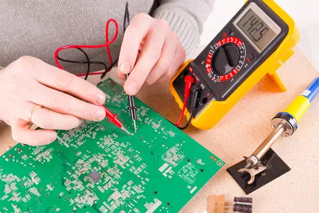
Step 3: Power Supply Check Using a Multimeter
Most PCB failures stem from power supply issues. Use a multimeter for PCB testing to check if the board is receiving the correct voltage. For example, many elevator control PCBs operate on 24V DC for logic circuits and higher voltages for relays or motor controls. Refer to the board's documentation for expected values.
- Set your multimeter to DC voltage mode.
- Probe the power input pins or terminals.
- If the voltage is outside the specified range (e.g., below 22V or above 26V for a 24V system), the issue may lie with the power supply unit rather than the PCB itself.
Step 4: Test Key Components
Focus on PCB component testing to isolate faulty parts. Common components to check include:
- Resistors: Use the multimeter's resistance mode to verify if values match the labeled specifications (e.g., a 1kΩ resistor should read close to 1000 ohms).
- Capacitors: Check for shorts or open circuits. A healthy capacitor should show infinite resistance after an initial charge reading.
- Diodes and Transistors: Test for proper forward and reverse bias behavior using the diode test mode on your multimeter.
- Relays: Listen for a clicking sound when power is applied, or test coil resistance (typically 50-500 ohms depending on the relay).
Step 5: Trace Signal Paths
If individual components test fine, the issue might be with signal integrity. Use an oscilloscope to check for proper waveforms at key points, such as communication lines between the PCB and sensors. For instance, a typical elevator control signal might operate at a frequency of 1-10 kHz, and deviations could indicate a fault.
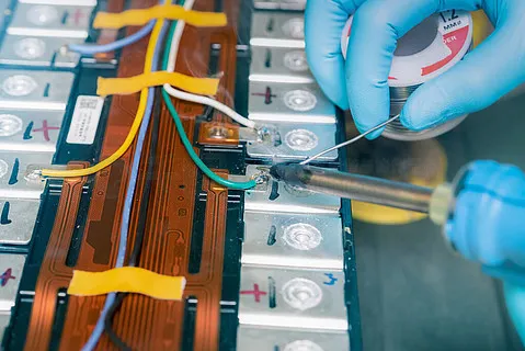
Step 6: Repair or Replace Faulty Components
Once you've identified the problem, proceed with elevator PCB repair. Use a soldering iron to remove and replace damaged components, ensuring you match the specifications exactly. For example, replacing a capacitor with the wrong voltage rating (e.g., using a 16V capacitor in a 24V circuit) can lead to immediate failure.
Advanced Tips for Elevator PCB Fault Finding
For more complex issues, consider these advanced techniques during elevator PCB fault finding:
- Thermal Imaging: Use a thermal camera to detect overheating components, which often indicate failing parts or poor circuit design. Hotspots above 80°C on a PCB are usually a red flag.
- Divide and Conquer: If the PCB has multiple sections (e.g., power, logic, and output), isolate each section by disconnecting connectors or cutting power to narrow down the fault area.
- Firmware Checks: Some elevator PCBs rely on microcontrollers with firmware. Ensure the firmware is up to date or reload it if corruption is suspected.
Preventive Maintenance to Avoid Future PCB Failures
Troubleshooting is only half the battle. To minimize future issues, follow these preventive maintenance tips:
- Regular Cleaning: Dust and debris can cause shorts or overheating. Clean PCBs every 6-12 months using non-conductive cleaners.
- Voltage Monitoring: Install surge protectors to prevent damage from power spikes, which can exceed 500V in some cases during electrical storms.
- Environmental Control: Keep control panels in environments with stable temperatures (ideally 15-25°C) and low humidity to prevent corrosion.
Challenges in Elevator PCB Repair and How to Overcome Them
Repairing elevator PCBs isn't always straightforward. Here are some common challenges and solutions:
- Obsolete Parts: Older elevator systems may use discontinued components. Search for equivalent parts with matching specs (e.g., a transistor with the same gain and voltage rating).
- Lack of Documentation: If schematics are unavailable, reverse-engineer the board by mapping connections manually or consult with industry peers for similar models.
- Complex Multilayer Boards: Modern PCBs may have hidden traces in internal layers. Use X-ray imaging if available, or focus on surface-level components first.
When to Seek Professional Help for Elevator PCB Repair
While many issues can be resolved with the steps above, some situations call for expert assistance. If the PCB has extensive damage (e.g., multiple burnt sections) or if troubleshooting reveals a design flaw rather than a component failure, it may be time to consult a specialized repair service. These services often offer rush repairs and warranties (sometimes up to 180 days), ensuring minimal downtime for critical systems.
Conclusion: Mastering Elevator Control PCB Troubleshooting
Troubleshooting and repairing elevator control PCBs is a vital skill for technicians responsible for maintaining safe and reliable elevator systems. By following a structured approach to elevator control PCB troubleshooting, using tools like a multimeter for PCB testing, and prioritizing preventive maintenance, you can minimize downtime and enhance safety. From visual inspections to advanced PCB component testing, each step plays a crucial role in effective elevator PCB repair.
At ALLPCB, we understand the importance of precision and reliability in electronic systems. While we focus on providing high-quality PCB manufacturing solutions, we’re committed to empowering technicians with the knowledge needed for successful fault finding and repairs. Keep this guide handy for your next elevator PCB fault finding task, and ensure your elevators keep moving without a hitch.


