 ALLPCB


If you're designing or troubleshooting a fitness tracker PCB and facing issues like noise, interference, or inconsistent data, signal integrity is likely the culprit. In this comprehensive guide, we’ll dive into common signal integrity problems in fitness tracker PCBs, such as noise, crosstalk, and signal reflection, and provide practical solutions to ensure your device performs reliably. Whether you're dealing with impedance mismatches or unwanted interference, we’ve got you covered with actionable tips to optimize your design.
Introduction: Why Signal Integrity Matters in Fitness Tracker PCBs
Fitness trackers are compact, high-tech devices packed with sensors, microcontrollers, and wireless communication modules. These components work together to monitor heart rate, steps, and other metrics, often in real-time. However, the small size of these devices means that signal paths are close together, increasing the risk of noise and interference. Poor signal integrity in a PCB can lead to inaccurate readings, dropped connections, or even complete device failure.
Signal integrity refers to the quality of an electrical signal as it travels from one point to another on a PCB. When designing fitness trackers, maintaining signal integrity is crucial to ensure data accuracy and device reliability. In this blog, we’ll explore the main challenges—like fitness tracker noise, crosstalk on PCBs, impedance matching issues, and signal reflection—and offer troubleshooting tips to resolve them.
Understanding Signal Integrity Challenges in Fitness Tracker PCBs
Before diving into solutions, let’s break down the core signal integrity issues that affect fitness tracker PCBs. These devices operate in a noisy environment, both electrically and physically, due to user movement and nearby electronic devices. Here are the primary challenges:
- Noise: Unwanted electrical signals can interfere with the accurate transmission of data from sensors to the processor.
- Crosstalk: Signals from adjacent traces can interfere with each other, especially in compact designs.
- Signal Reflection: Mismatched impedances can cause signals to bounce back, leading to data errors.
- Impedance Matching Issues: Incorrect impedance along signal paths can degrade performance, especially in high-speed circuits.
Addressing these issues requires a deep understanding of PCB design principles tailored to the unique constraints of wearable devices like fitness trackers.
Common Causes of Fitness Tracker Noise and Interference
Noise in fitness trackers often stems from multiple sources, both internal and external. Identifying the root cause is the first step to troubleshooting. Here are some common culprits:
1. Electromagnetic Interference (EMI)
Fitness trackers are often worn in environments with other electronic devices, such as smartphones or Wi-Fi routers, which can emit electromagnetic waves. These waves can couple with the PCB traces, introducing noise into the system. For example, a nearby Bluetooth signal operating at 2.4 GHz can interfere with a fitness tracker’s wireless module if proper shielding isn’t in place.
2. Power Supply Noise
A poorly designed power supply or inadequate decoupling capacitors can introduce ripples or spikes in the voltage supply. These fluctuations can affect sensor readings, especially for sensitive components like heart rate monitors, which often operate with signals in the millivolt range.
3. Ground Plane Issues
An improperly designed ground plane can create ground loops or insufficient return paths for signals. This can lead to noise coupling between different sections of the PCB, particularly in compact fitness tracker designs where space is limited.
Crosstalk in PCBs: A Hidden Threat to Fitness Tracker Performance
Crosstalk on PCBs occurs when a signal from one trace induces an unwanted signal in a nearby trace. In fitness trackers, where traces are packed tightly due to size constraints, crosstalk is a significant concern. For instance, a high-speed data line running parallel to a sensor signal line can introduce errors in heart rate or step count readings.
The severity of crosstalk depends on several factors:
- Trace Spacing: Traces closer than 3 times the trace width are more prone to crosstalk.
- Signal Frequency: Higher frequencies, such as those used in Bluetooth modules (up to 2.4 GHz), increase the risk of interference.
- Lack of Shielding: Without proper ground planes or shielding between traces, crosstalk becomes more likely.
To minimize crosstalk, designers can increase spacing between critical traces, use ground planes as barriers, or route high-speed signals on different layers of the PCB.
Signal Reflection and Impedance Matching: Key Factors in High-Speed Designs
Signal reflection happens when a signal encounters a change in impedance along its path, causing part of the signal to bounce back. This is a common issue in fitness trackers with high-speed interfaces, such as SPI or I2C lines used for sensor communication. Reflections can distort signals, leading to timing errors or data corruption.
Impedance matching is the solution to preventing reflections. For example, a typical high-speed signal line might require a controlled impedance of 50 ohms. If the trace impedance deviates significantly—say, to 70 ohms due to improper trace width or dielectric material—reflections will occur. Tools like impedance calculators can help ensure traces are designed with the correct dimensions based on the PCB stack-up.
Here are key tips for achieving proper impedance matching:
- Use consistent trace widths and spacing for critical signals.
- Match the impedance of connectors and components to the trace impedance.
- Consider the dielectric constant of your PCB material, as it affects signal speed and impedance. For instance, FR-4 material typically has a dielectric constant of around 4.5 at 1 MHz.
Troubleshooting Tips for Signal Integrity Issues in Fitness Tracker PCBs
Now that we’ve identified the main signal integrity challenges, let’s walk through practical troubleshooting steps to address noise, crosstalk, and signal reflection in fitness tracker PCBs. These tips are designed to help engineers pinpoint and resolve issues efficiently.
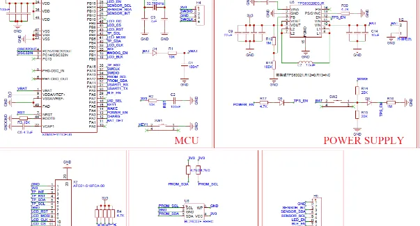
1. Start with a Thorough Design Review
Before fabricating a PCB, review the schematic and layout for potential signal integrity risks. Check for:
- Trace lengths and spacing, especially for high-speed signals.
- Placement of decoupling capacitors near power pins of ICs (ideally within 0.1 inches).
- Continuous ground planes with minimal cuts or splits.
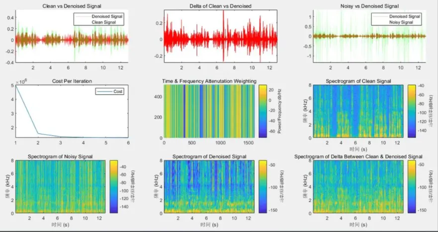
2. Use Simulation Tools for Signal Integrity Analysis
Simulation software can predict signal integrity issues before production. Tools can model crosstalk, signal reflection, and impedance mismatches, allowing you to adjust your design. For example, simulating a 100 MHz signal on a trace can reveal if reflections exceed acceptable thresholds, such as a 10% overshoot.
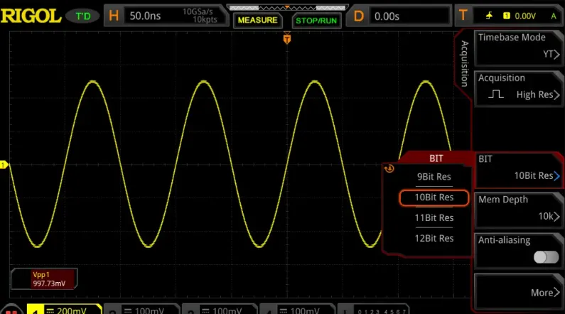
3. Test with an Oscilloscope for Real-Time Diagnostics
Once the PCB is built, use an oscilloscope to measure signals at critical points. Look for noise spikes, ringing (indicative of reflections), or unexpected signal coupling. For instance, if a sensor output shows periodic noise at 50 Hz, it might indicate interference from a nearby power line.
4. Add Proper Filtering and Shielding
To reduce noise, incorporate low-pass filters on sensor lines to block high-frequency interference. Additionally, use shielding techniques, such as enclosing sensitive components in a Faraday cage or adding guard traces around critical signals, to minimize EMI.
5. Optimize Power Delivery Network (PDN)
Ensure the power supply is stable by placing decoupling capacitors close to ICs. A typical setup might include a 0.1 μF capacitor for high-frequency noise and a 10 μF capacitor for bulk energy storage. This helps maintain a clean voltage supply, reducing noise in sensor readings.
Best Practices for Designing Fitness Tracker PCBs with Strong Signal Integrity
Prevention is always better than troubleshooting. Here are some best practices to design fitness tracker PCBs that minimize signal integrity issues from the start:
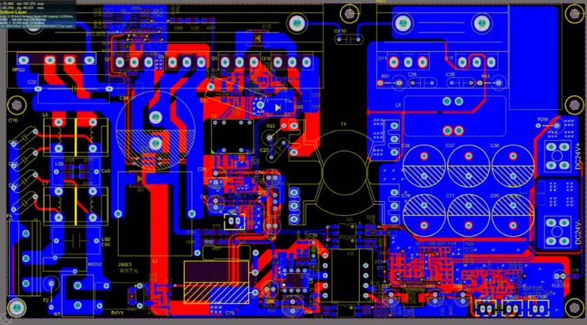
- Keep High-Speed Traces Short: Minimize the length of traces carrying high-speed signals to reduce the risk of reflections and noise pickup.
- Use Multi-Layer Boards: A 4-layer PCB with dedicated power and ground planes offers better shielding and return paths compared to a 2-layer board.
- Route Signals Strategically: Avoid running sensitive analog traces parallel to digital lines to prevent crosstalk.
- Select Appropriate Materials: Choose PCB materials with stable dielectric properties for high-frequency signals, especially if your fitness tracker includes wireless communication.
Case Study: Solving Noise in a Fitness Tracker Prototype
Consider a real-world example where a fitness tracker prototype showed inconsistent heart rate readings. Initial testing revealed noise spikes on the sensor output, particularly when the user moved. Using an oscilloscope, the design team identified interference at 2.4 GHz, matching the frequency of the device’s wireless module.
The solution involved rerouting the sensor traces away from the wireless module and adding a ground plane between them. Additionally, a small shielding enclosure was placed around the wireless module to contain EMI. After these changes, the noise reduced by over 80%, and heart rate readings became stable even during movement.
This case highlights the importance of isolating sensitive signals and using proper shielding to maintain signal integrity in fitness tracker PCBs.
Conclusion: Building Reliable Fitness Tracker PCBs with Strong Signal Integrity
Signal integrity is the backbone of reliable fitness tracker performance. By addressing challenges like fitness tracker noise, crosstalk on PCBs, signal reflection, and impedance matching, you can ensure accurate data collection and seamless user experience. From thorough design reviews to real-time testing with oscilloscopes, the troubleshooting tips and best practices shared in this guide provide a roadmap to success.
Designing compact devices like fitness trackers comes with unique constraints, but with careful planning and attention to signal integrity, you can overcome noise and interference challenges. Keep these strategies in mind during your next PCB design project to create wearables that perform flawlessly under any condition.


