In the high-stakes world of military radar systems, ensuring flawless performance is non-negotiable. One of the key factors in achieving this is optimizing printed circuit board (PCB) design for superior signal integrity. This blog post dives deep into the essentials of military radar PCB design, focusing on critical aspects like impedance control, signal integrity simulation, and high-frequency layout techniques. Whether you're an engineer working on defense projects or a designer aiming to improve radar performance, you'll find actionable insights on controlled impedance routing and signal reflection minimization right here.
Why Signal Integrity Matters in Military Radar PCB Design
Signal integrity refers to the quality of an electrical signal as it travels through a PCB. In military radar systems, where precision and reliability can mean the difference between safety and disaster, poor signal integrity can lead to data loss, interference, or system failure. Radar systems often operate at high frequencies, sometimes exceeding 10 GHz, making them particularly vulnerable to issues like crosstalk, electromagnetic interference (EMI), and signal reflections.
Maintaining signal integrity ensures that radar signals are transmitted and received accurately, enabling precise detection and tracking. This is why optimizing PCB design for military radar applications involves careful planning and advanced techniques to address challenges unique to high-frequency environments.
Key Challenges in Military Radar PCB Design
Designing PCBs for military radar systems comes with unique challenges due to the demanding operational conditions and performance requirements. Here are some of the primary hurdles engineers face:
- High-Frequency Signals: Radar systems often operate in the microwave range (1 GHz to 100 GHz), where signal loss and distortion become significant issues.
- Harsh Environments: Military equipment must withstand extreme temperatures, vibrations, and humidity, which can affect PCB materials and performance.
- Miniaturization: Modern radar systems require compact designs, forcing engineers to pack high-density components into smaller spaces without sacrificing signal quality.
- EMI and Crosstalk: The proximity of components and high-frequency signals increases the risk of interference, which can degrade radar accuracy.
Addressing these challenges requires a focus on specialized design practices tailored for military applications, which we’ll explore in the following sections.
Mastering Military Radar PCB Impedance Control
Impedance control is a cornerstone of signal integrity in high-frequency PCB designs, especially for military radar systems. Impedance refers to the resistance a signal encounters as it travels through a trace on the PCB. If the impedance isn’t consistent, signals can reflect back, causing distortion or loss.
In military radar PCB impedance control, designers aim for a specific impedance value, often around 50 ohms for RF (radio frequency) applications, to match the connected components and transmission lines. Mismatched impedance can lead to signal reflections, reducing the radar’s ability to detect targets accurately. For example, a mismatch of just 10% can result in a signal loss of up to 0.5 dB, which is significant in high-precision systems.
To achieve controlled impedance, engineers must carefully select PCB materials with stable dielectric constants (Dk), typically between 3.0 and 4.5 for high-frequency applications. They also need to calculate trace widths and spacing using impedance calculators or simulation tools, ensuring consistency across the board.
Leveraging Signal Integrity Simulation for Radar PCBs
Signal integrity simulation is a powerful tool for predicting and resolving potential issues before manufacturing a PCB. In military radar design, where trial-and-error is not an option, simulation helps engineers analyze how signals behave under various conditions.
Simulation software can model factors like signal delay, crosstalk, and reflections at frequencies as high as 40 GHz or more. For instance, a simulation might reveal that a trace routed too close to a power plane causes a 20% increase in crosstalk, allowing designers to adjust the layout before production. These tools also help in optimizing stack-up designs, ensuring that signal layers are separated by ground planes to minimize interference.
By incorporating signal integrity simulation early in the design process, engineers can save time and reduce costs while ensuring the radar system meets stringent military standards. This proactive approach is essential for handling the complex, high-frequency signals typical of radar applications.
Best Practices for High-Frequency PCB Layout in Radar Systems
A well-thought-out high-frequency PCB layout is critical for maintaining signal integrity in military radar systems. At frequencies above 1 GHz, even small layout errors can lead to significant performance issues. Here are some best practices to follow:
- Minimize Trace Lengths: Shorter traces reduce signal loss and the risk of interference. For example, a trace longer than 10 cm at 10 GHz can introduce a delay of over 50 picoseconds, affecting timing accuracy.
- Use Ground Planes: Place continuous ground planes beneath signal layers to provide a stable return path and reduce EMI. Avoid splitting ground planes, as gaps can create impedance discontinuities.
- Avoid Sharp Corners: Route traces with smooth curves or 45-degree angles instead of 90-degree turns to prevent signal reflections.
- Separate High-Speed and Low-Speed Signals: Keep high-frequency radar signals away from slower digital signals to prevent crosstalk.
These practices ensure that the PCB layout supports the high-frequency requirements of radar systems, delivering reliable performance even under demanding conditions.
Controlled Impedance Routing Techniques
Controlled impedance routing goes hand-in-hand with impedance control to ensure signals travel without distortion. This technique involves designing PCB traces to maintain a consistent impedance value throughout their length, which is crucial for military radar systems operating at microwave frequencies.
One effective method is differential pair routing, often used for high-speed signals. Differential pairs consist of two traces carrying complementary signals, and their impedance is controlled by maintaining precise spacing (typically 0.2 to 0.5 mm) and matching lengths to within 0.1 mm. This minimizes noise and ensures signal integrity.
Another approach is to use microstrip or stripline configurations. Microstrip traces, placed on the outer layers of the PCB, are easier to fabricate but more susceptible to EMI. Stripline traces, sandwiched between ground planes, offer better shielding but require precise layer stack-up planning. For radar systems, stripline is often preferred due to its superior noise immunity.
By implementing controlled impedance routing, designers can significantly reduce signal degradation, ensuring accurate data transmission in military radar applications.
Signal Reflection Minimization Strategies
Signal reflections occur when a signal encounters an impedance mismatch, sending part of the signal back toward the source. In military radar systems, reflections can distort waveforms, leading to errors in target detection. Signal reflection minimization is, therefore, a top priority.
One key strategy is to terminate traces properly using resistors or other components that match the characteristic impedance of the line. For example, a 50-ohm termination resistor at the end of a trace can absorb the signal, preventing reflections. Without proper termination, up to 30% of the signal energy can reflect back, causing interference.
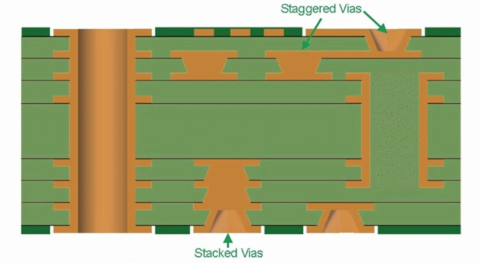
Another approach is to avoid vias in high-frequency signal paths. Vias introduce inductance and capacitance, creating impedance discontinuities. If vias are unavoidable, designers should use back-drilling to remove unused portions, reducing their impact.
Finally, careful material selection plays a role. Using low-loss materials with a dielectric constant tolerance of ±0.05 can help maintain consistent impedance, further reducing reflections.
Material Selection for Military Radar PCBs
The choice of materials is a critical factor in military radar PCB design. High-frequency signals require substrates with low dielectric loss and stable properties across a wide temperature range (-55°C to 125°C for military standards).
Common materials for radar PCBs include high-frequency laminates with dielectric constants between 2.2 and 3.5, offering low signal loss at frequencies up to 40 GHz. These materials also provide thermal stability, ensuring consistent performance in harsh environments.
Additionally, copper thickness and surface finish must be considered. A copper thickness of 1 oz (35 μm) is often used for high-frequency traces to balance conductivity and manufacturability. Surface finishes like immersion gold protect against oxidation while maintaining signal quality.
Selecting the right materials ensures that the PCB can handle the high-frequency, high-stress demands of military radar systems without compromising signal integrity.
Testing and Validation for Signal Integrity
Once a military radar PCB is designed, thorough testing is essential to validate signal integrity. This includes both simulation and physical testing to ensure the board meets performance requirements.
Time-domain reflectometry (TDR) is a common method for measuring impedance along traces. A TDR test can detect mismatches as small as 1 ohm, helping engineers identify and fix issues before deployment. Frequency-domain testing, using vector network analyzers (VNAs), measures signal loss and reflections at specific frequencies, often up to 50 GHz for radar applications.
Environmental testing is also crucial for military PCBs. Boards must be subjected to thermal cycling, vibration, and humidity tests to simulate battlefield conditions. Passing these tests ensures the PCB will perform reliably in real-world scenarios.
By combining simulation with rigorous testing, designers can confidently deliver radar PCBs that meet the highest standards of signal integrity and durability.
Conclusion: Building Reliable Military Radar PCBs
Optimizing military radar PCB design for enhanced signal integrity is a complex but essential task. By focusing on military radar PCB impedance control, leveraging signal integrity simulation, and applying best practices for high-frequency PCB layout, engineers can create boards that perform flawlessly under the most demanding conditions. Techniques like controlled impedance routing and signal reflection minimization further ensure that radar systems deliver accurate, reliable results.
At every stage—from material selection to testing—attention to detail is key. With the right approach, designers can overcome the challenges of high-frequency design and build PCBs that support the critical missions of military radar systems. Trust in proven design strategies and advanced tools to achieve unparalleled performance in your next project.
 ALLPCB


