 ALLPCB


Elevator control systems are the backbone of safe and efficient building operations, and the printed circuit boards (PCBs) within these systems must be designed for high reliability. If you're searching for elevator PCB design rules or high-reliability PCB design tips, you're in the right place. This blog dives deep into the essential considerations for creating robust elevator control PCBs that withstand harsh environments, manage thermal stress, and ensure long-term performance. Let’s explore the key aspects of elevator PCB layout and design to help you build dependable systems.
Why High-Reliability Matters in Elevator Control PCBs
Elevator control PCBs are critical components that manage everything from motor control to safety mechanisms. A failure in these boards can lead to downtime, safety hazards, or costly repairs. High-reliability PCB design is not just a preference—it’s a necessity. These boards often operate in harsh environments with temperature fluctuations, vibrations, and electrical noise, making durability and precision in design paramount.
In this guide, we’ll cover the core principles of designing elevator control PCBs, focusing on layout rules, thermal management, and strategies for harsh conditions. Whether you're an engineer or a designer, these insights will help you create boards that meet the stringent demands of elevator systems.
Key Challenges in Elevator PCB Design
Before diving into specific design rules, it’s important to understand the unique challenges elevator control PCBs face. These systems are often exposed to:
- Temperature Extremes: Elevator control units may be located in unconditioned spaces like machine rooms or basements, where temperatures can range from -10°C to 50°C or higher.
- Vibration and Mechanical Stress: Constant movement of elevator cars introduces vibrations that can loosen components or cause micro-cracks in solder joints.
- Electrical Noise: High-power motors and switching circuits generate electromagnetic interference (EMI) that can disrupt signal integrity.
- Long-Term Operation: Elevators are expected to run 24/7 for decades, requiring PCBs to resist wear and degradation over time.
Addressing these challenges starts with a thoughtful approach to PCB design for harsh environments. Let’s break down the essential considerations.
Elevator PCB Design Rules for High Reliability
Designing a reliable elevator control PCB requires adherence to strict guidelines. Below are key elevator PCB design rules to ensure durability and performance.
1. Choose the Right Materials
The foundation of any high-reliability PCB is the material used. For elevator control systems, consider:
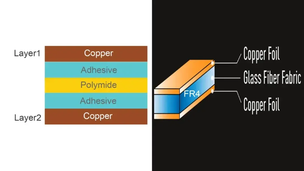
- High-Tg FR-4 or Polyimide: Standard FR-4 laminates may suffice for basic applications, but high-Tg (glass transition temperature) FR-4 or polyimide materials are better suited for harsh environments. High-Tg materials can withstand temperatures up to 170°C without deforming, compared to standard FR-4’s limit of around 130°C.
- Thicker Copper Layers: Use copper layers of at least 2 oz/ft2 for power traces to handle high currents (often 5-10A or more in elevator motor control circuits) and improve heat dissipation.
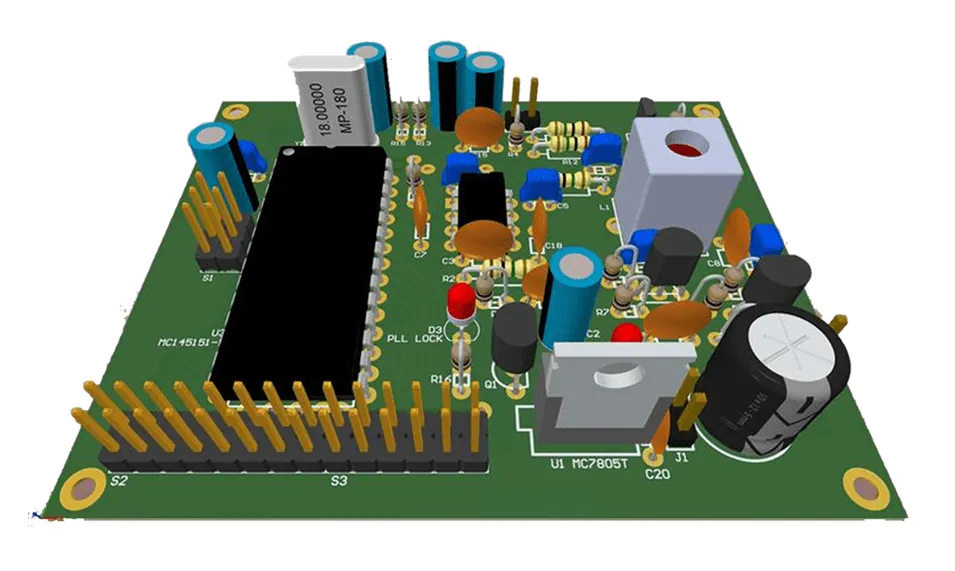
2. Optimize Component Placement
Component placement in elevator PCB layout is critical for reliability and signal integrity. Follow these tips:
- Place heat-generating components like power transistors or voltage regulators away from sensitive analog circuits to minimize thermal interference.
- Position high-voltage components (handling 24V to 48V typical in elevator systems) with adequate spacing to prevent arcing. A clearance of at least 0.5 mm per 100V is a good rule of thumb.
- Group related components (e.g., motor control ICs and their capacitors) closely to reduce trace lengths and minimize EMI.
3. Ensure Robust Grounding and Shielding
Electrical noise from motors and relays can wreak havoc on elevator control signals. To combat this:
- Use a solid ground plane to provide a low-impedance return path for currents, reducing noise. Split the ground plane into analog and digital sections if mixed signals are present.
- Implement shielding for sensitive areas by adding guard traces or copper pours around high-frequency signal lines.
Elevator PCB Layout Best Practices
A well-thought-out elevator PCB layout can make the difference between a board that lasts a few years and one that endures for decades. Here are actionable layout tips for high reliability.
1. Minimize Trace Lengths for Signal Integrity
Long traces can act as antennas, picking up EMI or causing signal delays. For elevator control systems, where response times are critical (e.g., safety interlocks reacting within 10 ms), keep traces short. Aim for trace lengths under 10 cm for high-speed signals (above 1 MHz) to avoid signal degradation.
2. Use Wide Traces for High-Current Paths
Elevator systems often involve high currents for motor drives. Narrow traces can overheat or fail under load. Use trace width calculators to ensure traces can handle the current. For example, a 10A current on a 1 oz copper layer requires a trace width of at least 2.5 mm at 25°C ambient temperature to prevent excessive heating (above 10°C temperature rise).
3. Avoid Right-Angle Traces
Right-angle traces can cause signal reflection in high-speed circuits and are more prone to manufacturing defects. Use 45-degree angles or curved traces for smoother signal flow and better reliability, especially for control signals operating at frequencies above 100 kHz.
PCB Design for Harsh Environments
Elevator control PCBs often operate in less-than-ideal conditions. Designing for harsh environments ensures they can handle the stress without failing.
1. Protect Against Moisture and Dust
Elevator machine rooms can be dusty or humid, leading to corrosion or short circuits. Apply these protective measures:
- Use conformal coatings (e.g., acrylic or silicone-based) to shield the PCB from moisture and contaminants. Ensure the coating can withstand temperatures up to 85°C without degrading.
- Opt for sealed connectors with IP65 or higher ratings to prevent dust ingress at connection points.
2. Design for Vibration Resistance
Vibrations from elevator operation (often in the range of 1-5 Hz with amplitudes up to 0.5 mm) can loosen components or crack solder joints. To mitigate this:
- Use surface-mount components (SMD) over through-hole parts where possible, as they have lower profiles and are less likely to vibrate loose.
- Secure larger components (like electrolytic capacitors) with adhesive or mechanical fasteners.
- Avoid placing components near board edges or mounting holes, where mechanical stress is highest.
PCB Thermal Management for Elevator Control Systems
Heat is a major enemy of PCB reliability. Poor thermal management can lead to component failure, reduced lifespan, or erratic performance. Here’s how to address thermal challenges in elevator PCB design.
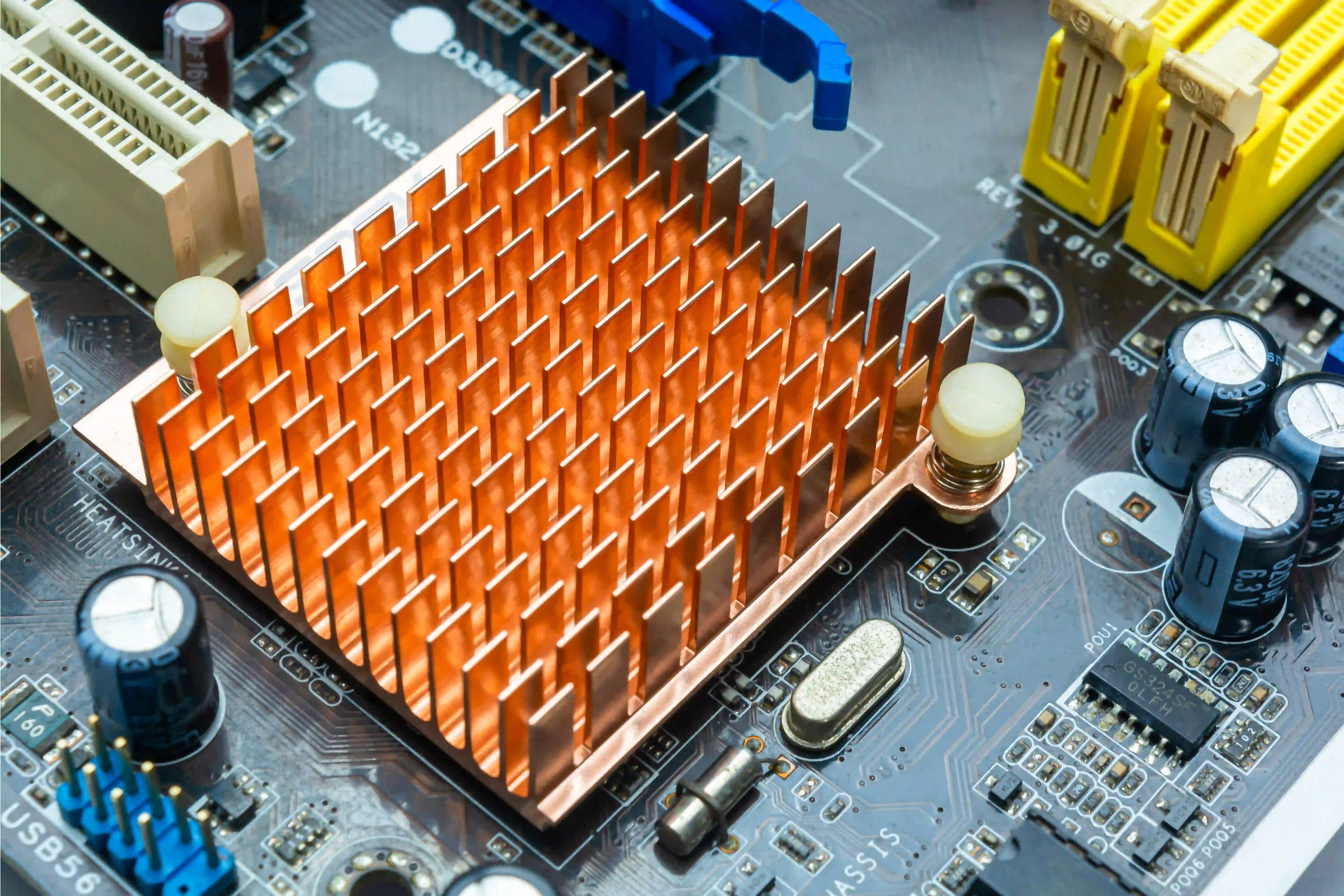
1. Incorporate Heat Sinks and Thermal Vias
Components like power MOSFETs or regulators in elevator motor control circuits can generate significant heat (often dissipating 5-10W or more). To manage this:
- Attach heat sinks to high-power components, ensuring they are sized to keep junction temperatures below 125°C (check component datasheets for maximum ratings).
- Add thermal vias under heat-generating components to transfer heat to the opposite side of the board or to a dedicated copper plane. A grid of 0.3 mm vias spaced 1.2 mm apart can reduce thermal resistance by up to 50%.
2. Optimize Copper Planes for Heat Dissipation
Large copper planes act as natural heat spreaders. Dedicate inner layers or unused areas of the board to copper pours connected to ground or power planes. This can lower the board’s overall temperature by 5-10°C under high load conditions (e.g., continuous motor operation at 8A).
3. Monitor and Simulate Thermal Performance
Before finalizing your design, use thermal simulation tools to predict hot spots. Aim to keep critical components below 85°C during operation, even at maximum ambient temperatures of 50°C. Adjust component placement or add cooling solutions if simulations show excessive heat buildup.
Testing and Validation for High-Reliability PCB Design
Designing a high-reliability PCB is only half the battle. Rigorous testing ensures the board performs as expected in real-world conditions.
- Environmental Testing: Subject the PCB to temperature cycling (e.g., -20°C to 80°C for 100 cycles) and humidity tests (85% RH at 85°C for 96 hours) to simulate harsh environments.
- Vibration Testing: Test the board under vibration profiles mimicking elevator operation (1-10 Hz, 0.5 mm amplitude) to verify component stability.
- Electrical Testing: Measure signal integrity and power delivery under full load to ensure no voltage drops or noise issues. For example, confirm that a 24V supply line maintains stability within ±5% during motor startup surges.
Conclusion: Building Elevator Control PCBs That Last
Designing high-reliability elevator control PCBs requires careful attention to material selection, layout rules, and environmental challenges. By following elevator PCB design rules, optimizing your elevator PCB layout, and prioritizing PCB thermal management, you can create boards that endure the harsh conditions of elevator systems. Whether it’s managing vibrations, protecting against EMI, or ensuring thermal stability, each step contributes to a safer and more dependable system.


