 ALLPCB


If you're looking for a way to ensure reliable and long-lasting connections in high-wear applications, hard gold plating for edge connectors is a proven solution. Often used in printed circuit board (PCB) designs, this technique—commonly associated with "gold fingers"—provides exceptional durability and resistance to wear, making it ideal for connectors that are frequently plugged and unplugged. In this blog, we'll dive deep into why hard gold plating is essential for edge connectors, how it enhances PCB connector performance, and key design guidelines including plating thickness to help you make informed decisions for your projects.
What Are Edge Connectors and Gold Fingers?
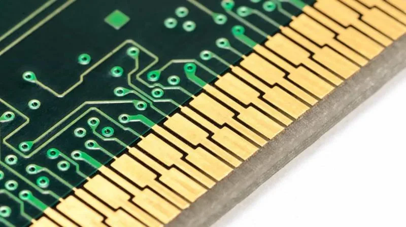
Edge connectors, often referred to as "gold fingers" in the PCB industry, are the gold-plated pads or contacts located along the edge of a circuit board. These connectors are designed to interface with a slot or socket in a larger system, enabling communication, power transfer, or data exchange between boards or devices. You’ll find them in everyday electronics like computer memory modules, graphics cards, and industrial control systems.
The term "gold fingers" comes from the shiny, finger-like appearance of these plated contacts. But beyond aesthetics, the gold plating serves a critical purpose: it protects the connector from wear, corrosion, and oxidation, ensuring a stable electrical connection even after thousands of insertion cycles. Hard gold plating, in particular, is a specialized process that enhances these properties for high-wear applications.
Why Hard Gold Plating for Edge Connectors?
Gold is a preferred material for plating edge connectors due to its excellent conductivity and resistance to corrosion. However, not all gold plating is the same. Hard gold plating stands out because it is alloyed with small amounts of other metals like cobalt or nickel, making it more durable and wear-resistant than soft gold. Here’s why hard gold plating is critical for edge connectors in high-wear scenarios:
- Durability: Hard gold can withstand up to 10,000 insertion cycles without significant wear, compared to soft gold, which may start degrading after just a few hundred cycles.
- Corrosion Resistance: Gold does not oxidize easily, ensuring that the contact resistance remains low—often below 10 milliohms—even in humid or harsh environments.
- Friction Resistance: The harder surface reduces damage from mechanical abrasion during repeated mating and unmating of connectors.
- Signal Integrity: With a conductivity rating of approximately 41.6 MS/m (megasiemens per meter), gold ensures minimal signal loss, making it ideal for high-speed applications like PCIe cards operating at data rates of 8 GT/s or higher.
For applications like aerospace, medical devices, and industrial machinery where reliability is non-negotiable, hard gold plating is often the go-to choice for edge connectors.
Applications of Hard Gold Plating in PCB Connectors
Hard gold plating is widely used across industries where edge connectors face frequent use or harsh conditions. Some common applications include:
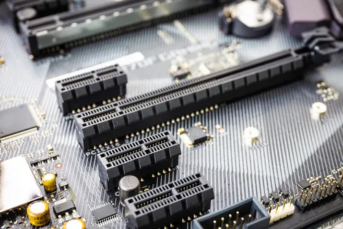
- Computer Hardware: Memory modules (DIMMs) and expansion cards like GPUs rely on gold fingers for stable connections with motherboards.
- Industrial Equipment: Control boards in manufacturing systems often use edge connectors for modularity, requiring durable plating to handle vibrations and frequent swaps.
- Medical Devices: Diagnostic equipment with removable modules needs reliable connectors to ensure accurate data transfer without signal degradation.
- Aerospace and Defense: Systems exposed to extreme temperatures and humidity benefit from the corrosion resistance of hard gold.
In each of these cases, hard gold plating ensures that the connectors maintain performance over time, reducing the risk of failures that could lead to costly downtime or safety issues.
Related Reading: The Ultimate Guide to Hard Gold Plating for PCBs: Applications, Processes, and Best Practices
Edge Connector Plating Thickness: How Much Gold Is Enough?
One of the most critical factors in designing edge connectors with hard gold plating is determining the right plating thickness. Too thin, and the plating may wear out quickly; too thick, and it becomes unnecessarily expensive without added benefits. The plating thickness is typically measured in microinches (μin) or micrometers (μm), and industry standards provide clear guidelines.
For most high-wear applications, a hard gold plating thickness of 30 to 50 microinches (0.76 to 1.27 μm) over a nickel underlayer of 50 to 150 microinches (1.27 to 3.81 μm) is recommended. Here’s why this range works:
- 30 μin (0.76 μm): Suitable for applications with moderate insertion cycles (around 500 to 1,000). It provides a balance of durability and cost.
- 50 μin (1.27 μm): Ideal for high-wear applications with 5,000 or more cycles. This thickness ensures longevity without excessive gold usage.
- Nickel Underlayer: The nickel base layer prevents diffusion between the gold and the underlying copper, enhancing adhesion and wear resistance. A thickness of 100 μin (2.54 μm) is often the sweet spot for most designs.
Exceeding 50 μin of gold can lead to issues like cracking due to the brittleness of hard gold at higher thicknesses. On the other hand, going below 30 μin risks exposing the nickel underlayer during wear, which can increase contact resistance and lead to signal issues.
Always consult with your PCB manufacturer to confirm the plating thickness based on your specific application and budget. Standards like IPC-6012 (Qualification and Performance Specification for Rigid Printed Boards) can also provide detailed guidance on acceptable ranges.
Related Reading: Mastering Hard Gold Plating Thickness: Balancing Cost, Performance, and Reliability
Edge Connector Design Guidelines for Optimal Performance
Designing edge connectors with hard gold plating requires careful attention to several factors beyond just plating thickness. Poor design can negate the benefits of gold plating, leading to premature wear or unreliable connections. Below are some key edge connector design guidelines to follow:
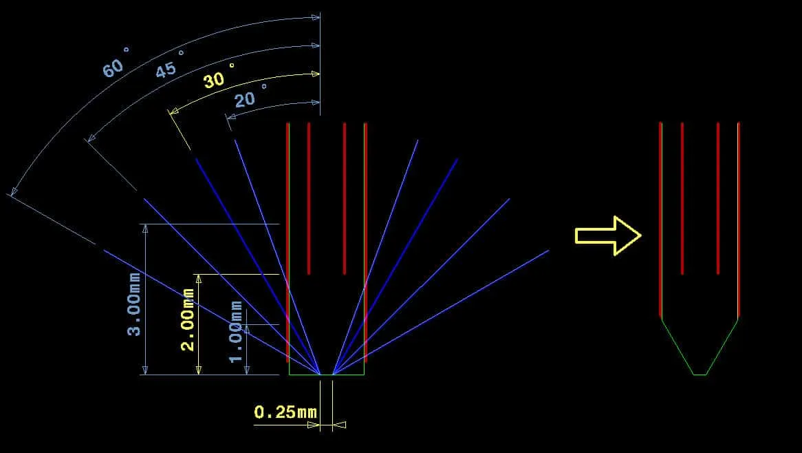
1. Beveling for Smooth Insertion
Edge connectors often feature a beveled edge to facilitate smooth insertion into a socket. A bevel angle of 30 to 45 degrees is standard, as it reduces mechanical stress on the gold plating during mating. This small detail can significantly extend the lifespan of the connector.
2. Pad Spacing and Width
The spacing and width of the gold fingers should match the mating connector’s specifications to avoid misalignment. A typical pad width for standard edge connectors is 0.031 inches (0.8 mm) with a spacing of 0.1 inches (2.54 mm) between centers, though this varies based on the application.
3. Avoid Overlapping Solder Mask
Ensure that the solder mask does not overlap the gold-plated area. Any contamination or residue on the gold fingers can increase contact resistance, which might lead to intermittent connections. A clear boundary of at least 0.005 inches (0.127 mm) between the solder mask and the plated area is recommended.
4. Connector Length and Insertion Depth
Design the length of the gold fingers to match the insertion depth of the socket. If the plated area extends beyond the contact zone, it’s a waste of gold. Conversely, if it’s too short, the connection may be unstable. A typical insertion depth for standard connectors is around 0.25 inches (6.35 mm), but this should be verified with the socket design.
5. Environmental Considerations
For applications in harsh environments, consider additional protective measures like conformal coatings for the non-contact areas of the PCB. While hard gold resists corrosion, other parts of the board may still be vulnerable to moisture or chemicals.
Hard Gold vs. Other Plating Options: A Comparison
While hard gold plating is ideal for many high-wear applications, it’s not the only option for edge connectors. Understanding how it compares to alternatives can help you choose the right finish for your project. Here’s a quick comparison:
- Hard Gold: Best for high-wear, high-reliability applications. Offers excellent durability (up to 10,000 cycles) and corrosion resistance but is more expensive due to material costs.
- Soft Gold: Used for applications requiring wire bonding rather than frequent insertions. It’s less durable (around 200 cycles) but cheaper than hard gold.
- ENIG (Electroless Nickel Immersion Gold): A cost-effective option for moderate wear applications. It provides good corrosion resistance but typically wears out after 500 to 1,000 cycles due to its thinner gold layer (2-5 μin or 0.05-0.13 μm).
- Tin Plating: The most affordable option, but it’s prone to oxidation and fretting corrosion, making it unsuitable for high-reliability or high-wear scenarios.
For edge connectors in demanding applications, hard gold plating often justifies its higher cost through superior performance and longevity.
Challenges and Cost Considerations of Hard Gold Plating
While hard gold plating offers unmatched reliability for edge connectors, it comes with challenges and costs that designers must consider:
- Cost: Gold is expensive, and the thicker the plating, the higher the price. A board with 50 μin of hard gold plating can cost 20-30% more than one with ENIG, depending on the size and number of connectors.
- Manufacturing Complexity: Hard gold plating requires precise control during the electrolytic plating process to ensure uniform thickness and adhesion. This can increase lead times.
- Limited Flexibility: Hard gold is brittle compared to softer finishes, so it’s not ideal for applications where the connector may experience bending or flexing.
To manage costs, consider using selective plating, where only the edge connector area is plated with hard gold, while the rest of the board uses a cheaper finish like ENIG. This hybrid approach balances performance and budget effectively.
How to Ensure Quality in Hard Gold Plated Edge Connectors
Quality control is essential when working with hard gold plated edge connectors. Here are some steps to ensure you get the best results:
- Specify Requirements Clearly: Provide detailed specifications for plating thickness, nickel underlayer, and bevel angles in your design files.
- Work with Reputable Manufacturers: Choose a PCB fabrication partner with experience in hard gold plating and adherence to industry standards like IPC-6012.
- Test for Durability: Request samples or perform insertion cycle testing to verify that the connectors meet your reliability expectations. A common test standard is MIL-G-45204, which outlines wear and corrosion resistance requirements for gold plating.
- Inspect for Defects: Look for signs of uneven plating, pinholes, or contamination on the gold fingers, as these can compromise performance.
Conclusion: Investing in Hard Gold Plating for Long-Term Reliability
Hard gold plating for edge connectors is a game-changer for high-wear applications, offering unmatched durability, corrosion resistance, and signal integrity. Whether you're designing PCB connectors for consumer electronics, industrial systems, or critical aerospace equipment, gold fingers with hard gold plating ensure reliable performance over thousands of insertion cycles. By following edge connector design guidelines and choosing the right plating thickness—typically 30 to 50 microinches—you can optimize both performance and cost.
At ALLPCB, we understand the importance of precision and reliability in every project. Our expertise in hard gold plating and PCB manufacturing ensures that your edge connectors meet the highest standards for durability and performance. Ready to bring your design to life with robust, long-lasting connections? Let us help you craft the perfect solution tailored to your needs.


