 ALLPCB


In the fast-evolving world of automotive technology, infotainment systems have become a cornerstone of the driving experience, blending entertainment, navigation, and connectivity into a seamless interface. But what many may not realize is that the performance of these systems heavily depends on the design of the printed circuit board (PCB) at their core. A well-optimized PCB layout can make the difference between a smooth, responsive infotainment system and one plagued by glitches, delays, or interference. In this blog, we’ll explore how PCB layout optimization for infotainment systems, along with signal routing techniques on PCBs, ground plane design in automotive applications, and power plane design considerations, directly impacts system performance. Let’s dive into the details of creating high-performing designs for modern vehicles.
Why PCB Layout Matters for Infotainment Systems
Infotainment systems in vehicles are complex, combining high-speed data processing, audio-visual outputs, and wireless connectivity. These systems handle signals ranging from low-frequency audio to high-frequency data for touchscreens and Bluetooth connections. A poorly designed PCB layout can lead to signal interference, power instability, and electromagnetic compatibility (EMC) issues, all of which degrade the user experience. On the other hand, a carefully planned layout ensures minimal noise, efficient power distribution, and reliable signal integrity, resulting in crisp audio, fast response times, and uninterrupted connectivity.
For engineers working on automotive electronics, understanding the impact of PCB layout is critical. The layout influences not just performance but also the durability and safety of the system, as automotive environments are harsh, with temperature fluctuations, vibrations, and electromagnetic interference (EMI) from other vehicle components. Let’s break down the key aspects of PCB design that affect infotainment system performance.
Key Elements of PCB Layout Optimization for Infotainment
Optimizing a PCB layout for infotainment systems involves several critical factors. Each element must be carefully considered to ensure the system operates flawlessly under the demanding conditions of a vehicle. Below are the core areas of focus for PCB layout optimization for infotainment.
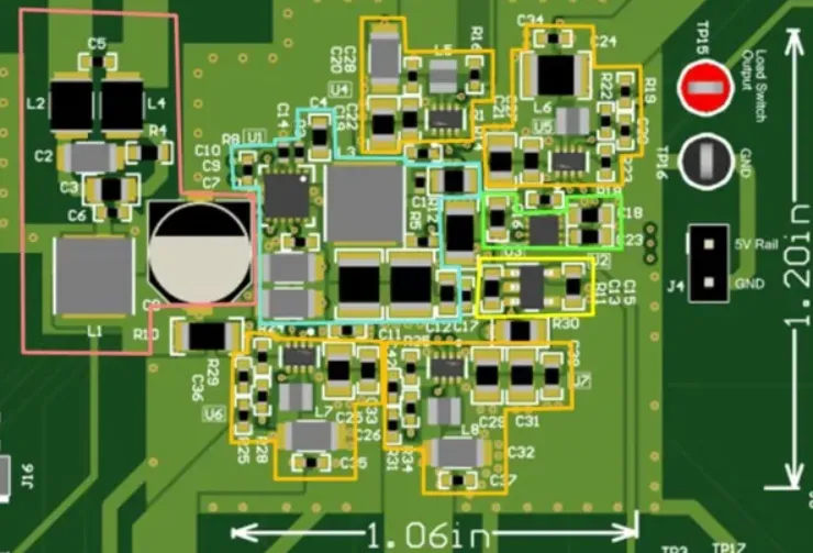
1. Component Placement for Efficiency and Heat Management
The placement of components on a PCB directly affects signal paths and heat dissipation. In infotainment systems, high-power components like processors and amplifiers generate significant heat. Placing these components near heat sinks or away from sensitive analog circuits can prevent thermal interference. Additionally, grouping related components together—such as keeping digital and analog sections separate—reduces the risk of noise coupling. For example, placing a high-speed processor too close to an audio amplifier without proper shielding can introduce unwanted noise into the audio output, leading to a poor listening experience.
Engineers should also consider the physical constraints of the automotive environment. Infotainment PCBs often need to fit into tight spaces within the dashboard, so optimizing component placement for a compact layout without sacrificing performance is essential. Using simulation tools to predict heat distribution and signal behavior can help achieve an efficient design before prototyping.
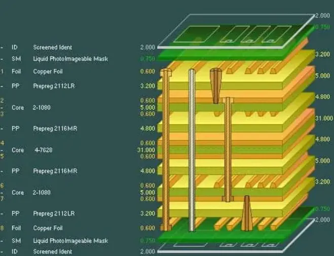
2. Layer Stack-Up for Signal and Power Integrity
Modern infotainment systems often require multi-layer PCBs to handle the complexity of signals and power needs. A typical stack-up might include 4 to 8 layers, with dedicated layers for power, ground, and signal routing. A well-designed stack-up ensures that high-speed signals, such as those for video displays (often running at frequencies above 1 GHz), are isolated from power lines to prevent interference. For instance, placing a ground layer between a high-speed signal layer and a power layer can act as a shield, reducing crosstalk and EMI.
A common practice is to use a symmetrical stack-up to minimize board warpage under thermal stress, which is particularly important in automotive applications where temperature can range from -40°C to 85°C. By optimizing the layer arrangement, engineers can achieve better signal integrity and power stability, directly enhancing the performance of infotainment systems.
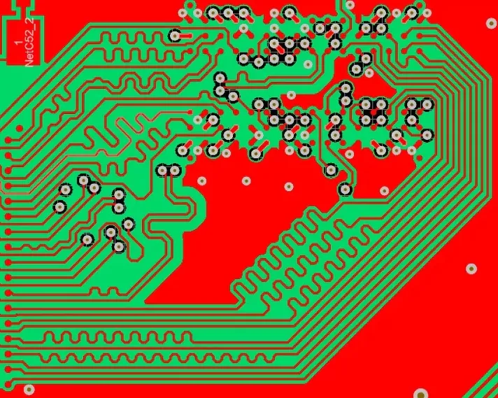
Signal Routing Techniques on PCBs for High-Speed Performance
One of the most critical aspects of PCB design for infotainment systems is signal routing. With the high-speed data demands of modern systems—think video streaming or real-time navigation updates—effective signal routing techniques on PCBs are non-negotiable. Poor routing can lead to signal delays, reflections, or crosstalk, all of which degrade system performance. Here are some proven strategies for optimal signal routing.
1. Minimize Signal Path Lengths
Shorter signal paths reduce the chance of signal degradation and delay. For high-speed signals, such as those used in USB or HDMI connections within infotainment systems, engineers aim to keep trace lengths as short as possible. For example, a USB 2.0 signal running at 480 Mbps requires careful routing to avoid timing mismatches between differential pairs. A mismatch of even 100 mils (2.54 mm) can introduce significant skew, leading to data errors.
2. Use Differential Pair Routing for High-Speed Signals
Many signals in infotainment systems, like those for touchscreens or high-definition video, use differential pairs to improve noise immunity. Routing these pairs with equal lengths and consistent spacing ensures that the signals arrive at their destination simultaneously, minimizing errors. Maintaining a controlled impedance—often around 90 ohms for USB differential pairs—is also critical to prevent reflections. PCB design software can help calculate and maintain the correct trace width and spacing for the desired impedance.
3. Avoid Sharp Corners in Traces
For high-frequency signals, sharp 90-degree corners in traces can cause signal reflections due to impedance discontinuities. Instead, use 45-degree angles or rounded corners to maintain signal integrity. This small adjustment can significantly reduce EMI, ensuring clearer video and audio output in infotainment systems.
Ground Plane Design in Automotive Applications
A solid ground plane design in automotive systems is essential for reducing noise and ensuring stable operation. The ground plane serves as a reference point for all signals and a return path for currents, making it a cornerstone of signal integrity and EMI control in infotainment systems.
1. Use a Continuous Ground Plane
A continuous, unbroken ground plane on a dedicated layer provides a low-impedance path for return currents, reducing the risk of ground loops and noise. In automotive infotainment systems, where EMI from nearby components like engines or alternators is a constant threat, a solid ground plane acts as a shield. Avoid splitting the ground plane unless absolutely necessary, as splits can create high-impedance paths and increase noise.
2. Separate Analog and Digital Grounds
Infotainment systems often combine analog audio circuits with digital processors, and mixing their ground returns can introduce noise into sensitive analog signals. A common approach is to use a split ground plane, connecting the analog and digital sections at a single point (often near the power supply) to minimize interference. This technique ensures that digital switching noise doesn’t affect audio quality, providing a better user experience.
3. Place Ground Vias Strategically
In multi-layer PCBs, ground vias connect the ground plane to component pins across layers. Placing vias close to high-speed components ensures a short return path, reducing inductance and noise. For instance, placing ground vias near the pins of a high-frequency processor can prevent signal integrity issues, maintaining the responsiveness of the infotainment interface.
Power Plane Design Considerations for Stability
Power delivery is another critical factor in infotainment system performance, and power plane design considerations play a major role in ensuring stability. A poorly designed power distribution network can lead to voltage drops, ripple, and thermal issues, all of which impact system reliability.
1. Dedicate Layers for Power Distribution
In multi-layer PCBs, dedicating a layer to power distribution ensures a low-impedance path for current, minimizing voltage drops. For infotainment systems, which may require multiple voltage levels (e.g., 3.3V for digital circuits and 5V for displays), separate power planes or wide traces can prevent cross-contamination between power domains. This approach helps maintain stable operation even under heavy load, such as when streaming video and processing navigation data simultaneously.
2. Use Decoupling Capacitors Effectively
Decoupling capacitors placed near power pins of ICs help filter out noise and stabilize voltage. For high-speed processors in infotainment systems, a combination of bulk capacitors (10-100 μF) and smaller ceramic capacitors (0.1-1 μF) can address both low-frequency and high-frequency noise. Positioning these capacitors as close as possible to the power pins—ideally within 100 mils (2.54 mm)—reduces inductance and ensures a clean power supply.
3. Manage Thermal Load on Power Planes
High-current components in infotainment systems, such as audio amplifiers, can generate significant heat. Designing power planes with adequate copper thickness (e.g., 2 oz/ft2 or higher) helps dissipate heat and prevents voltage drops. Additionally, adding thermal vias under high-power components can transfer heat to other layers or a heat sink, protecting the PCB from damage in the harsh automotive environment.
Testing and Validation for Optimal Performance
After designing a PCB layout for an infotainment system, thorough testing and validation are crucial to ensure performance meets expectations. Signal integrity analysis can identify issues like crosstalk or reflections, often using tools to simulate eye diagrams for high-speed signals. For example, an eye diagram for a 1 Gbps signal should show a clear opening, indicating minimal jitter and noise. EMI testing in an anechoic chamber can also confirm that the design complies with automotive standards like CISPR 25, which limits radiated emissions in vehicles.
Thermal testing under extreme conditions (e.g., -40°C to 85°C) ensures the PCB can withstand the automotive environment without warpage or component failure. By validating the design at every stage, engineers can fine-tune the layout for maximum reliability and performance.
Conclusion: Building Better Infotainment Systems with PCB Layout
The performance of automotive infotainment systems hinges on the quality of the PCB layout. From PCB layout optimization for infotainment to advanced signal routing techniques on PCBs, every design decision impacts signal integrity, power stability, and user experience. By focusing on critical areas like ground plane design in automotive applications and power plane design considerations, engineers can create robust systems that deliver seamless entertainment and connectivity, even under the toughest conditions.
At ALLPCB, we understand the unique challenges of designing PCBs for automotive applications. Our expertise and advanced manufacturing capabilities help bring your infotainment designs to life with precision and reliability. Whether you’re working on a compact dashboard system or a complex multimedia hub, a well-optimized PCB layout is the foundation of success. Let’s build the future of automotive technology together.


