 ALLPCB


If you're looking to design a rigid-flex PCB stackup that thrives in harsh environments, you’ve come to the right place. Whether it's for aerospace, medical devices, or automotive applications, a robust rigid-flex stackup ensures reliability under extreme temperatures, vibrations, and other challenging conditions. In this blog, we’ll guide you through the entire process—from concept to creation—focusing on practical design tips for rigid-flex stackup reliability, and specific considerations for rigid-flex PCB for aerospace, rigid-flex PCB for medical devices, rigid-flex PCB for automotive, and extreme temperature rigid-flex applications.
Let’s dive into the details of designing a stackup that not only meets your project needs but also withstands the toughest environments.
What is a Rigid-Flex PCB Stackup?
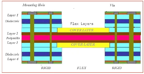
A rigid-flex PCB combines the stability of rigid circuit boards with the adaptability of flexible circuits. The stackup refers to the arrangement of layers—both rigid and flexible—along with insulating materials and conductive traces that form the complete board structure. This hybrid design is ideal for applications where space is limited, and durability is critical, such as in aerospace systems, medical implants, and automotive electronics.
Designing a rigid-flex stackup for harsh environments requires careful planning to balance flexibility, strength, and performance. Factors like material selection, layer configuration, and thermal management play a huge role in ensuring rigid-flex stackup reliability. In the following sections, we’ll break down each step of the design process to help you build a board that performs under pressure.
Why Rigid-Flex PCBs Excel in Harsh Environments
Harsh environments—think extreme temperatures ranging from -55°C to 125°C, high vibration levels, or exposure to moisture and chemicals—demand electronics that won’t fail. Rigid-flex PCBs are uniquely suited for these conditions because they offer:
- Space Efficiency: Their ability to bend and fold reduces the need for connectors, saving space in compact devices like medical wearables or automotive sensors.
- Durability: Fewer connectors mean fewer points of failure, enhancing reliability in high-stress applications like aerospace control systems.
- Thermal Resistance: With the right materials, rigid-flex boards can handle extreme temperature rigid-flex scenarios, such as those found in engine compartments or space missions.
Understanding these benefits is the first step to designing a stackup that meets the specific needs of your industry. Let’s explore how to tailor your design for different applications.
Key Considerations for Rigid-Flex Stackup Design in Harsh Environments
Creating a rigid-flex PCB for harsh environments involves several critical factors. Below, we’ll cover the most important aspects to ensure rigid-flex stackup reliability.
1. Material Selection for Durability
The materials you choose for your rigid-flex stackup directly impact its performance in extreme conditions. Here are some guidelines:
- Base Materials: Use polyimide (PI) for flexible layers due to its excellent thermal stability (up to 260°C) and resistance to chemicals. For rigid layers, high-Tg FR4 (glass transition temperature above 170°C) offers strength and heat resistance.
- Adhesives: Opt for adhesiveless laminates in high-temperature applications to prevent delamination. These are especially critical for extreme temperature rigid-flex designs.
- Copper Thickness: Choose copper weights between 1 oz and 3 oz per square foot to balance flexibility and current-carrying capacity, ensuring reliability in high-vibration settings.
By selecting materials suited to your environment, you lay a strong foundation for a durable stackup.
2. Layer Configuration for Optimal Performance
The arrangement of rigid and flexible layers in your stackup affects both functionality and reliability. A typical rigid-flex stackup might include 4 to 8 layers, with flexible layers in the middle and rigid layers on the outside. Here’s what to consider:
- Layer Count: Keep the layer count as low as possible to reduce complexity and cost while meeting signal integrity needs. For high-speed designs, a 6-layer stackup (2 rigid, 2 flex, 2 rigid) often works well.
- Bend Radius: Ensure the flexible section’s bend radius is at least 10 times the thickness of the flex layer to prevent cracking. For example, a 0.1 mm thick flex layer should have a minimum bend radius of 1 mm.
- Transition Zones: Reinforce areas where rigid and flex layers meet with stiffeners or additional material to avoid stress fractures during vibration or thermal cycling.
Proper layer configuration ensures your board can handle mechanical stress while maintaining electrical performance.
3. Thermal Management for Extreme Temperatures
Thermal management is critical for extreme temperature rigid-flex applications. Temperature swings can cause expansion and contraction, leading to material fatigue. Here’s how to address this:
- Heat Dissipation: Integrate copper planes or thermal vias to spread heat evenly across the board. For instance, a copper plane with a thickness of 2 oz can significantly reduce hot spots in automotive engine control units.
- Material CTE Matching: Choose materials with similar coefficients of thermal expansion (CTE) to minimize stress. Polyimide has a CTE of about 20-30 ppm/°C, which pairs well with high-Tg FR4 at 14-18 ppm/°C.
- Testing: Subject your design to thermal cycling tests (e.g., -40°C to 85°C for 1000 cycles) to simulate real-world conditions and ensure reliability.
Effective thermal management keeps your rigid-flex PCB performing even in the harshest climates.
Industry-Specific Design Tips for Rigid-Flex PCBs
Different industries have unique requirements for rigid-flex PCBs. Let’s look at tailored approaches for aerospace, medical, and automotive applications to ensure rigid-flex stackup reliability.
Rigid-Flex PCB for Aerospace
In aerospace, rigid-flex PCBs face extreme conditions like temperature variations from -55°C to 125°C, high vibration (up to 20G), and cosmic radiation. Here’s how to design a rigid-flex PCB for aerospace:
- Lightweight Design: Minimize weight by reducing layer count and using thin materials (e.g., 0.05 mm polyimide) without sacrificing strength.
- Radiation Hardening: Use materials and shielding techniques to protect against radiation-induced signal degradation.
- Signal Integrity: Maintain controlled impedance (typically 50-100 ohms) for high-speed signals in navigation and communication systems by carefully spacing traces and using ground planes.
These steps ensure your board can handle the rigors of space or high-altitude flight.
Rigid-Flex PCB for Medical Devices
Medical devices, such as pacemakers or wearable monitors, require compact, reliable designs that operate in the human body or during sterilization processes. For a rigid-flex PCB for medical devices, consider:
- Biocompatibility: Use materials that meet ISO 10993 standards for biocompatibility to ensure safety in contact with the body.
- Miniaturization: Design with tight trace widths (down to 0.075 mm) and spacing to fit into small devices while maintaining flexibility for bending or folding.
- Reliability: Test for moisture resistance (e.g., IPX7 standards) to protect against bodily fluids or cleaning processes.
These considerations make your rigid-flex PCB safe and effective for critical healthcare applications.
Rigid-Flex PCB for Automotive
Automotive electronics, such as engine control units or infotainment systems, must withstand heat, vibration, and humidity. For a rigid-flex PCB for automotive, focus on:
- Thermal Endurance: Use materials that handle temperatures up to 150°C near engines. High-Tg FR4 and polyimide are ideal choices.
- Vibration Resistance: Add stiffeners and secure mounting points to prevent flexing or cracking under vibration levels of 5-10G.
- Signal Speed: Ensure high-speed data transfer (e.g., for CAN bus systems at 1 Mbps) by optimizing trace routing and minimizing crosstalk.
These design elements keep your board reliable on the road, no matter the conditions.
Steps to Design a Robust Rigid-Flex Stackup
Now that we’ve covered the key factors and industry-specific needs, let’s walk through the practical steps to design your rigid-flex stackup for harsh environments.
Step 1: Define Requirements
Start by outlining the environmental conditions and performance needs of your application. For example, will the board face temperatures above 100°C? Does it need to bend repeatedly without failing? Clear requirements guide your material and design choices.
Step 2: Select Materials and Stackup
Based on your requirements, choose materials and configure your stackup. Use simulation tools to test different layer arrangements and ensure they meet mechanical and electrical goals, like maintaining 50-ohm impedance for high-speed signals.
Step 3: Design for Manufacturability
Work closely with your manufacturing partner to ensure your design can be produced without issues. For instance, avoid overly tight bend radii that could strain flexible layers during fabrication.
Step 4: Prototype and Test
Build a prototype and test it under simulated harsh conditions. For extreme temperature rigid-flex designs, use thermal chambers to cycle between -40°C and 125°C. For vibration, test at levels up to 10G to confirm durability.
Step 5: Refine and Finalize
Analyze test data to identify weaknesses, such as delamination or signal loss, and refine your design. Once satisfied, move to full-scale production with confidence in your stackup’s reliability.
Common Challenges and How to Overcome Them
Designing a rigid-flex stackup for harsh environments isn’t without challenges. Here are some common issues and solutions:
- Delamination: Prevent separation of layers by using adhesiveless laminates and matching CTE values between materials.
- Signal Integrity Loss: Minimize crosstalk and impedance mismatches by using ground planes and keeping high-speed traces short (under 10 cm if possible).
- Mechanical Stress: Reinforce bend areas with stiffeners and avoid sharp corners in trace routing to reduce stress points.
Addressing these challenges early in the design phase saves time and ensures a reliable final product.
Conclusion: Building Reliability into Every Layer
Designing a robust rigid-flex stackup for harsh environments is a complex but rewarding process. By focusing on material selection, layer configuration, and thermal management, you can create a board that excels in demanding applications. Whether you’re working on a rigid-flex PCB for aerospace, medical devices, or automotive systems, the principles of rigid-flex stackup reliability remain the same: prioritize durability, test rigorously, and tailor your design to the environment.
With these strategies, you can take your concept from idea to creation, confident that your rigid-flex PCB will perform under even the most extreme conditions. If you’re ready to start your next project, ensure you partner with a trusted manufacturer who understands the nuances of extreme temperature rigid-flex designs and beyond.


