 ALLPCB


For PCB designers, understanding inductor specifications is crucial to creating efficient and reliable circuits. Whether you're working on power supplies, filters, or RF applications, interpreting an inductor datasheet and grasping key parameters can make or break your design. In this guide, we’ll break down inductor datasheet interpretation, explain inductor parameters, and provide actionable insights for understanding inductor specifications for PCB design. Let’s dive into the essentials and help you navigate the complex world of inductors with confidence.
Why Inductor Specifications Matter in PCB Design
Inductors are passive components that store energy in a magnetic field when current flows through them. They’re vital in applications like DC-DC converters, noise suppression, and signal filtering on printed circuit boards. However, choosing the wrong inductor due to misinterpreting specifications can lead to circuit inefficiencies, overheating, or even failure. By mastering inductor datasheet interpretation, you ensure your design meets performance requirements and avoids costly redesigns.
In this blog, we’ll explore the key parameters of inductors, how to read datasheets, and practical tips for selecting the right component for your PCB layout. Let’s start with the basics and build up to advanced considerations.
What Are Inductors and Their Role in PCBs?
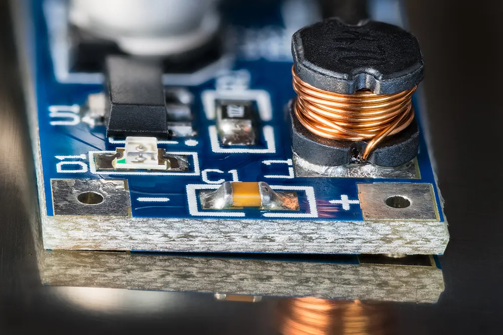
An inductor is a coil of wire, often wrapped around a core material like ferrite or iron, that resists changes in current by generating a magnetic field. In PCB design, inductors are used in various ways:
- Power Supplies: They smooth out voltage ripples in DC-DC converters.
- Signal Filtering: They block high-frequency noise while allowing low-frequency signals to pass.
- RF Circuits: They tune frequencies in oscillators and antennas.
Understanding how inductors work is the first step to understanding inductor specifications for PCB design. Each application demands specific inductor characteristics, which are detailed in datasheets. Let’s decode those specifications next.
Key Inductor Parameters Explained
When you open an inductor datasheet, you’re greeted with a range of technical terms and values. Here, we’ll break down the most critical inductor parameters explained in a way that’s easy to apply to your PCB projects.
1. Inductance (L)
Inductance, measured in Henries (H), microHenries (μH), or milliHenries (mH), indicates an inductor’s ability to store energy in a magnetic field. For example, a 10 μH inductor is common in small power supply circuits. This value is the cornerstone of inductor selection, as it directly affects how the component behaves in your circuit. A higher inductance means greater opposition to current changes, which is ideal for filtering but may slow down response in switching applications.
Tip: Always check the tolerance of the inductance value, often listed as ±10% or ±20%. A 10 μH inductor with ±10% tolerance could range from 9 μH to 11 μH, impacting performance if precision is critical.
2. Rated Current (I_Rated)
This parameter specifies the maximum continuous current the inductor can handle without overheating. Exceeding this value can cause thermal damage or performance degradation. For instance, if your circuit draws 2 A, select an inductor with a rated current of at least 2 A, preferably with some margin (e.g., 2.5 A) for safety.
3. Saturation Current (I_Sat)
Saturation current is the point at which the inductor’s core can no longer store additional magnetic energy, causing inductance to drop significantly. If your circuit experiences current spikes, ensure the saturation current is higher than the peak current. For example, in a buck converter with a peak current of 3 A, choose an inductor with an I_Sat of 3.5 A or more.
4. DC Resistance (DCR)
DC Resistance, measured in ohms (Ω) or milliohms (mΩ), represents the resistance of the inductor’s wire. A lower DCR means less power loss and higher efficiency, which is critical in power applications. For instance, a DCR of 50 mΩ in a 1 A circuit results in a voltage drop of 0.05 V and power loss of 0.05 W. Compare this across datasheets to minimize losses.
5. Self-Resonant Frequency (SRF)
The SRF is the frequency at which the inductor stops behaving like an inductor and starts acting like a capacitor due to parasitic effects. For RF designs, ensure the SRF is well above your operating frequency. If your circuit operates at 100 MHz, an inductor with an SRF of 150 MHz might not be suitable due to proximity to the operating range—aim for 200 MHz or higher.
6. Quality Factor (Q)
The Q factor measures the efficiency of an inductor at a specific frequency, especially important in RF circuits. A higher Q indicates lower energy loss and better performance in tuned circuits. Datasheets often provide Q values at specific frequencies, such as Q=40 at 1 MHz, guiding you in selecting components for oscillators or filters.
How to Interpret an Inductor Datasheet
Now that we’ve covered the key inductor parameters explained, let’s walk through inductor datasheet interpretation step by step. A typical datasheet provides a wealth of information, often in tables, graphs, and notes. Here’s how to navigate it effectively for your PCB design needs.
Step 1: Identify the Core Specifications
Start with the headline values: inductance, tolerance, rated current, and DCR. These are usually listed prominently in a summary table. For example, you might see “Inductance: 22 μH ±10%, Rated Current: 1.5 A, DCR: 0.08 Ω.” This gives you an immediate sense of whether the inductor fits your basic requirements.
Step 2: Check Application-Specific Parameters
Depending on your circuit, focus on relevant specs. For power supplies, prioritize saturation current and DCR. For RF designs, look at SRF and Q factor. Many datasheets include graphs showing inductance versus frequency or current, helping you visualize performance under different conditions.
Step 3: Review Physical and Environmental Specs
Don’t overlook size, mounting type (through-hole or surface-mount), and operating temperature range. A surface-mount inductor with dimensions of 3.2 mm x 2.5 mm might fit your compact PCB layout, but if it’s rated for -40°C to 85°C and your application operates at 100°C, it’s a no-go.
Step 4: Understand Test Conditions
Datasheets often specify test conditions for measurements, like “Inductance measured at 100 kHz, 0.1 V.” If your circuit operates far from these conditions, the actual performance might differ. Cross-check these details to avoid surprises.
Practical Tips for Selecting Inductors in PCB Design
With a solid grasp of understanding inductor specifications for PCB, let’s apply this knowledge to real-world design scenarios. Here are actionable tips to ensure you choose the right inductor for your project.
Match Inductance to Application Needs
For a low-pass filter in a power circuit, a higher inductance (e.g., 47 μH) helps smooth out ripples. In contrast, high-frequency switching converters often require lower inductance (e.g., 1 μH to 4.7 μH) to respond quickly to current changes. Calculate or simulate your circuit requirements using design tools to pinpoint the ideal value.
Account for Current Margins
Always select an inductor with a rated current and saturation current at least 20-30% above your circuit’s maximum expected current. This margin prevents overheating and ensures reliability during transient spikes. For a circuit with a steady 1 A draw and occasional 1.5 A peaks, opt for an inductor rated at 2 A with an I_Sat of 2 A or higher.
Minimize Power Loss with Low DCR
In battery-powered or high-efficiency designs, prioritize inductors with the lowest possible DCR within your budget. A difference of just 20 mΩ can significantly impact power loss in high-current applications. Balance this with size and cost constraints.
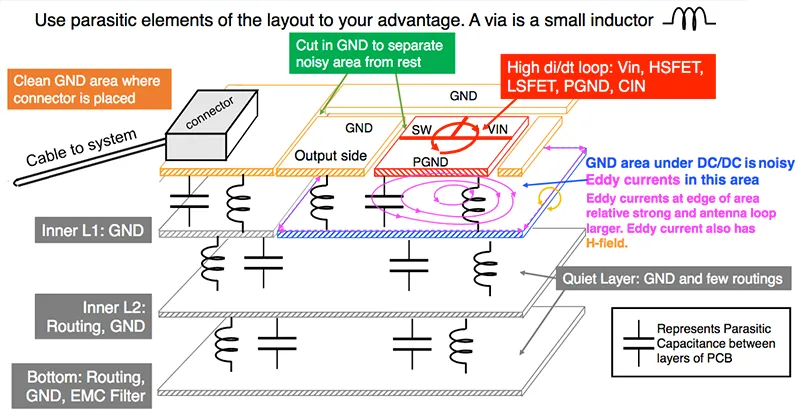
Consider Layout and Noise
Inductors can generate electromagnetic interference (EMI), so place them away from sensitive components like analog circuits. Use shielded inductors if noise is a concern, as they contain the magnetic field better than unshielded ones. Also, ensure trace lengths to and from the inductor are short to reduce parasitic effects.
Common Pitfalls to Avoid When Choosing Inductors
Even seasoned designers can trip up on inductor selection. Here are some mistakes to watch out for during inductor datasheet interpretation.
- Ignoring Saturation Current: Focusing only on rated current can lead to failure during current spikes. Always check I_Sat.
- Overlooking SRF in RF Designs: Using an inductor with an SRF too close to your operating frequency can distort signals.
- Neglecting Temperature Ratings: An inductor rated for 85°C max won’t survive in a 105°C environment, leading to premature failure.
- Skipping Derating: Operating at the maximum rated current or temperature reduces lifespan. Derate by 20-30% for longevity.
Advanced Considerations for Inductor Selection
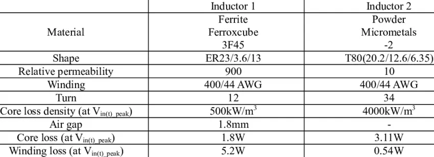
For complex designs, dive deeper into inductor behavior. Core material, for instance, affects performance—ferrite cores offer high inductance but lower saturation current, while powdered iron cores handle higher currents but with lower Q factors. Also, consider temperature coefficients if your PCB operates in varying conditions, as inductance can shift with heat.
In high-frequency designs, parasitic capacitance becomes significant. Datasheets might not list this directly, but it’s implied in SRF values. Simulate your circuit with estimated parasitics to predict real-world behavior.
Conclusion: Mastering Inductor Specifications for Better PCB Designs
Decoding inductor specifications doesn’t have to be daunting. By focusing on key parameters like inductance, rated current, saturation current, DCR, and SRF, you can confidently select components that match your PCB’s needs. Thorough inductor datasheet interpretation ensures you avoid common pitfalls and design circuits that perform reliably under real-world conditions.
Whether you’re a beginner or an experienced designer, keep this guide handy as a reference for understanding inductor specifications for PCB projects. With the right approach to inductor parameters explained, you’ll enhance efficiency, reduce noise, and build robust electronic systems. Start applying these insights in your next design, and watch your circuits come to life with precision and power.


