ALLPCB


In the fast-evolving world of hotel automation, high-density printed circuit boards (PCBs) are at the heart of room control systems, managing everything from lighting to HVAC systems. However, as these boards become more compact and powerful, managing heat becomes a critical challenge. Effective thermal management ensures reliability, longevity, and safety in these systems. This blog dives deep into proven strategies for PCB thermal design, heat sink selection, thermal vias, component placement, and airflow analysis tailored for hotel room control applications.
Whether you're an engineer designing PCBs for smart hotel systems or a manufacturer looking to optimize performance, this guide offers practical solutions to keep your boards cool under pressure. Let's explore how to tackle heat dissipation in high-density designs with actionable tips and detailed insights.
Why Thermal Management Matters in Hotel Room Control PCBs
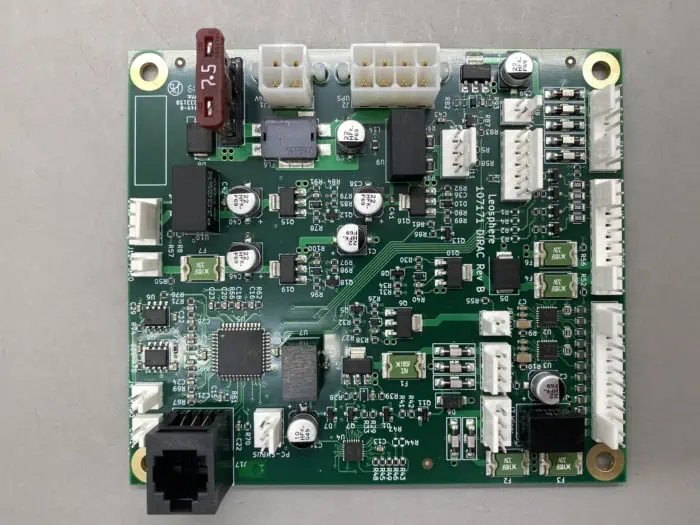
Hotel room control systems rely on compact PCBs to manage multiple functions like temperature regulation, lighting control, and security features. These high-density boards often pack numerous components into a small space, leading to significant heat generation. Without proper thermal management, excessive heat can cause component failure, reduce system efficiency, and even pose safety risks in a hospitality environment where reliability is non-negotiable.
Effective thermal management not only prevents overheating but also ensures consistent performance, extends the lifespan of the PCB, and reduces maintenance costs for hotel operators. With power densities in modern control systems often exceeding 10 W per square inch in critical areas, addressing heat dissipation through smart design is more important than ever.
Common Challenges in High-Density PCB Designs
High-density PCBs in hotel room control systems face unique thermal challenges:
- Compact Layouts: Limited space forces components closer together, reducing natural heat dissipation.
- High Power Components: Devices like microcontrollers and power regulators generate significant heat, often exceeding 5 W per component.
- Enclosed Environments: Control units are often housed in tight enclosures with limited airflow, trapping heat.
- Continuous Operation: These systems run 24/7, leaving little time for cooling.
Addressing these issues requires a multi-faceted approach, combining material choices, layout optimization, and active cooling solutions. Let's break down the key strategies to achieve effective thermal management.
Key Thermal Management Strategies for High-Density PCBs
1. PCB Thermal Design: Building a Foundation for Heat Dissipation
The foundation of thermal management starts with PCB thermal design. This involves selecting the right materials and designing the board layout to minimize heat buildup. For hotel room control systems, where space and reliability are critical, the following design principles are essential:
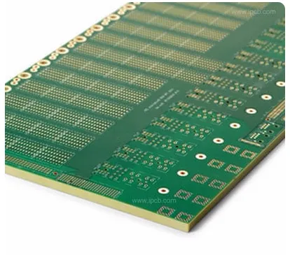
- Material Selection: Use substrates with high thermal conductivity, such as FR-4 with enhanced thermal properties or metal-core PCBs (MCPCBs). These materials can transfer heat away from components more effectively, with thermal conductivity values ranging from 1 to 3 W/m·K for advanced FR-4 variants.
- Copper Thickness: Opt for thicker copper layers (e.g., 2 oz or 70 μm) in power-heavy areas to act as a heat spreader, reducing localized hot spots.
- Layer Stack-Up: Design multi-layer boards with dedicated ground and power planes to distribute heat evenly across the board. A 4-layer board with internal copper planes can reduce thermal resistance by up to 20% compared to a 2-layer design.
By prioritizing these elements during the design phase, you can create a PCB that inherently manages heat better, reducing the need for additional cooling solutions.
2. Heat Sink Selection: Enhancing Passive Cooling
Heat sinks are a go-to solution for passive cooling in high-density PCBs. Proper heat sink selection can significantly reduce component temperatures, especially for high-power elements like voltage regulators and processors commonly found in hotel control systems. Consider the following when choosing a heat sink:
- Material: Aluminum is a popular choice due to its high thermal conductivity (around 200 W/m·K) and cost-effectiveness. For more demanding applications, copper heat sinks (thermal conductivity of 400 W/m·K) may be worth the added cost.
- Size and Shape: Select a heat sink size that matches the component’s heat output and available board space. Fin designs with larger surface areas improve heat dissipation by up to 30% compared to flat plate designs.
- Thermal Interface Material (TIM): Use high-quality thermal paste or pads between the component and heat sink to minimize thermal resistance. A good TIM can improve heat transfer efficiency by reducing interface resistance to below 0.5 °C/W.
For hotel room control PCBs, where space is often limited, low-profile heat sinks or heat spreaders integrated into the enclosure design can be effective without adding bulk.
3. Thermal Vias: Creating Pathways for Heat Transfer
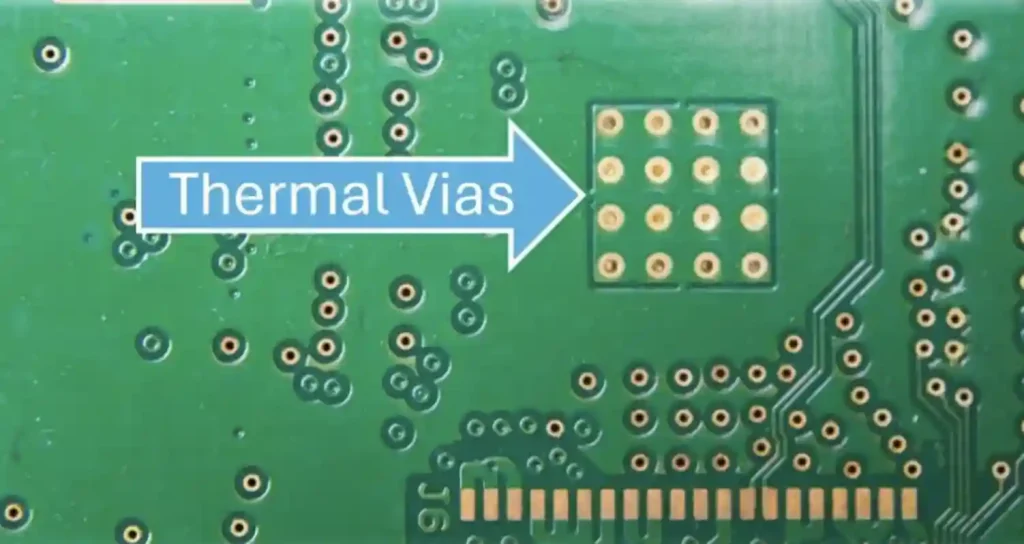
Thermal vias are small, copper-filled holes in the PCB that transfer heat from hot components on the surface to inner layers or the opposite side of the board. They are especially useful in high-density designs where space for heat sinks or airflow is limited. Here's how to use them effectively:
- Placement: Position thermal vias directly under or near heat-generating components like power ICs. A grid of 5x5 vias under a component can reduce its temperature by 5-10°C.
- Density and Size: Use vias with a diameter of 0.3-0.5 mm and space them 1-1.5 mm apart for optimal heat transfer without compromising board integrity.
- Connection to Planes: Connect thermal vias to ground or power planes to spread heat across larger copper areas. This can lower thermal resistance by up to 15% in multi-layer boards.
In hotel room control systems, where boards are often enclosed, thermal vias can be a game-changer by moving heat away from sensitive components without requiring additional space.
4. Component Placement: Optimizing Layout for Thermal Balance
Strategic component placement plays a huge role in managing heat on high-density PCBs. Poor placement can create hot spots, while a well-thought-out layout distributes heat evenly. Follow these tips for hotel room control PCBs:
- Separate Heat Sources: Place high-power components, such as power supplies or microprocessors, away from heat-sensitive parts like sensors. Maintain a minimum spacing of 5-10 mm between major heat sources to prevent thermal coupling.
- Centralize Cooling: Position high-heat components near areas with better access to cooling, such as near enclosure vents or heat sinks.
- Avoid Clustering: Distribute heat-generating components across the board rather than clustering them in one area. This can reduce peak temperatures by up to 8°C in densely populated designs.
Simulation tools can help predict thermal behavior during the layout phase, ensuring components are placed for optimal heat distribution before manufacturing begins.
5. Airflow Analysis: Maximizing Active and Passive Cooling
Airflow analysis is critical for ensuring that heat is effectively removed from the PCB, especially in enclosed hotel room control units. Whether using natural convection or forced airflow, understanding and optimizing air movement can make a significant difference:
- Natural Convection: Design enclosures with vents positioned to allow hot air to rise and escape while cooler air enters from below. Ensure a clear path for air movement around the PCB, with vent openings covering at least 10-15% of the enclosure surface area.
- Forced Air Cooling: For high-power systems, integrate small fans to create directed airflow over critical components. A fan providing 10-20 cubic feet per minute (CFM) can reduce board temperatures by 10-15°C.
- Simulation: Use computational fluid dynamics (CFD) tools to analyze airflow patterns and identify areas of stagnation. This can help optimize vent placement and fan positioning before physical prototyping.
In hotel environments, where noise and space constraints are concerns, balancing airflow with minimal fan usage or silent passive cooling designs is key to maintaining guest comfort.
Combining Strategies for Optimal Results
While each of these strategies—PCB thermal design, heat sink selection, thermal vias, component placement, and airflow analysis—is effective on its own, combining them creates a comprehensive thermal management plan. For example, pairing thermal vias with optimized component placement ensures heat is both dissipated locally and distributed evenly, while adding a well-selected heat sink and proper airflow tackles high-power areas effectively.
In a typical hotel room control PCB, you might use thermal vias under a 3 W microcontroller, place it near a vented area of the enclosure for natural airflow, and attach a small aluminum heat sink for additional cooling. This multi-layered approach can keep component temperatures below critical thresholds (typically 85°C for most ICs), ensuring reliable operation even under continuous use.
Tools and Techniques for Thermal Simulation
Before finalizing your PCB design, thermal simulation is a powerful way to predict and address heat issues. Tools like finite element analysis (FEA) and CFD software can model heat distribution and airflow, allowing you to test different layouts and cooling solutions virtually. For instance, simulating a board with a power density of 15 W/in2 can reveal hot spots exceeding 100°C, prompting adjustments like adding more vias or repositioning components.
Investing time in simulation early in the design process saves costly revisions later and ensures your hotel room control system meets performance and safety standards.
Conclusion: Keeping Hotel Room Control PCBs Cool and Reliable
Thermal management is a cornerstone of designing high-density PCBs for hotel room control systems. By implementing strategies like thoughtful PCB thermal design, careful heat sink selection, strategic use of thermal vias, optimized component placement, and thorough airflow analysis, you can prevent overheating and ensure reliable, long-lasting performance.
Start with a solid design foundation, use simulation tools to refine your approach, and combine multiple cooling methods for the best results. With these practices, your PCBs will not only handle the heat but also support the seamless, efficient operation of smart hotel systems, keeping guests comfortable and operations running smoothly.
At ALLPCB, we're committed to helping engineers and manufacturers achieve top-tier thermal performance in their designs. Explore our resources and services to bring your hotel room control systems to the next level with cutting-edge PCB solutions.