 ALLPCB


Overview
This application note describes using the CDBCAPTURE system with an embedded A/D converter. It explains the CDBCAPTURE system and provides examples for collecting data from an embedded ADC. The CDBCAPTURE board is intended to capture serial digital data from ADCs for measurement, analysis, and quantification of an analog front end's system performance. By analyzing measured performance, noise sources can be identified and corrective actions applied. CDBCAPTURE can be used as an engineering tool to reduce development time during system test and integration, and it can also be used in production to test finished units and verify system performance.
CDBCAPTURE Serial Interface
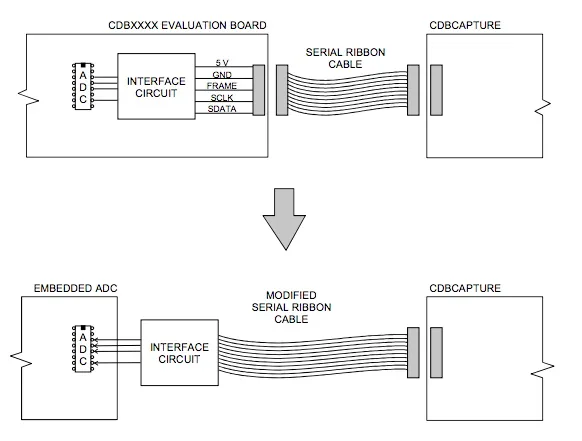
The CDBCAPTURE board is designed to connect directly to most Crystal Semiconductor ADC evaluation boards. That connection enables a straightforward method to quantify and verify ADC performance. However, when measuring ADC performance in a system, the ADC is often embedded and the digital interface circuitry resides on the system board. To capture data from an embedded ADC, a specially modified serial cable is required. The cable implements the digital interface circuitry present on the evaluation board and routes the corresponding signals from the ADC to the CAPTURE board.
Implementing the Embedded ADC Interface
Figure 1 conceptually shows how to implement the interface. On a typical evaluation board (CDBXXXX), the digital interface circuitry converts ADC outputs into three standard serial signals, commonly named FRAME, SCLK, and SDATA. Timing and format for these signals vary by device.
In an embedded application, the digital interface between the ADC and the CDBCAPTURE card should be implemented on a small adapter board that connects to the serial cable, as shown in the lower portion of Figure 1. Identify the appropriate digital input signals on the system board and implement a method to route those signals to the cable. The exact connection scheme depends on the application and can be implemented in several ways.
Refer to the evaluation board schematic to locate the serial interface connector with the signals: +5 V, GND, FRAME, SCLK, and SDATA. Trace these signals back to the ADC to determine the circuitry used to create the serial signals. Implement that circuitry on a separate board and connect it to a 10-conductor ribbon cable with an IDC socket that mates to the CDBCAPTURE interface. The ADC interface may use any convenient connector arrangement, such as pin headers, test clips, circular connectors, or D-sub connectors.
Example: CS5508
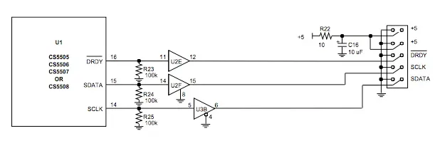
The following example uses the CS5508 to illustrate the process of designing a modified serial cable. By inspecting the CDB5508 evaluation board schematic, the digital interface circuitry is identified. The evaluation board schematic for CDB5505/6/7/8 shows the digital interface section illustrated in Figure 2. If the CS signal is permanently active, resistors R23, R24, and R25 are not required. Also, when the CAPTURE board is used, U3B remains active, so it may be replaced with a general buffer such as U2.
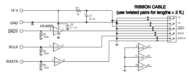
Modified Serial Cable Schematic
Figure 3 shows the schematic of the modified cable derived from Figure 2. The DRDY, SCLK, and SDATA signals are buffered to produce the serial cable signals for the CAPTURE board. The 5 V power is obtained from the embedded system, filtered through R1 and C1, and then supplied to the CAPTURE board. C2 is a bypass capacitor for U1.
Practical Use and Integration
The CDBCAPTURE system is intended to connect easily to most Crystal Semiconductor ADC evaluation boards. Evaluation boards typically include digital circuitry to implement a standard serial data bus. The CAPTURE board can be reconfigured via software to accommodate different ADCs and future products. CDBCAPTURE provides a convenient path to transfer digital data to a PC for analysis.
When an ADC operates inside a complete acquisition system, it is often necessary to capture its data while the ADC remains embedded in the electrical system. In these cases, the CAPTURE board's digital interface circuitry is implemented on a modified cable external to the system. The electrical system must provide an appropriate connection scheme, using connectors or test points that can be clamped.
The modified serial cable allows measurement of ADC performance while the ADC is embedded in the electrical system. Both ADC and overall system performance can be measured and quantified. This information supports isolation of issues and investigation of how subsystems interact.
Summary
By implementing the evaluation board digital interface circuitry on a small adapter and routing signals via a modified serial cable, CDBCAPTURE can be used to capture data from embedded ADCs. This enables engineers to analyze ADC and system performance in situ and supports troubleshooting and verification during development and production testing.


