 ALLPCB


Introduction
Automotive electronics operate in demanding conditions, including extreme temperatures, constant vibration, thermal cycling, and exposure to moisture. Aluminum PCBs, also known as metal core printed circuit boards, provide superior thermal conductivity and mechanical stability, making them ideal for aluminum PCB automotive applications. These boards help dissipate heat efficiently from power components, reducing the risk of failure under automotive PCB thermal stress. Engineers designing systems for engine controls, lighting, and electric vehicle inverters rely on aluminum PCB reliability to ensure long-term performance. As vehicles incorporate more electronics for advanced driver assistance and electrification, the need for robust substrates grows. This article explores how aluminum PCBs enhance reliability in such harsh environments.
What Are Aluminum PCBs and Why Do They Matter in Automotive Applications?
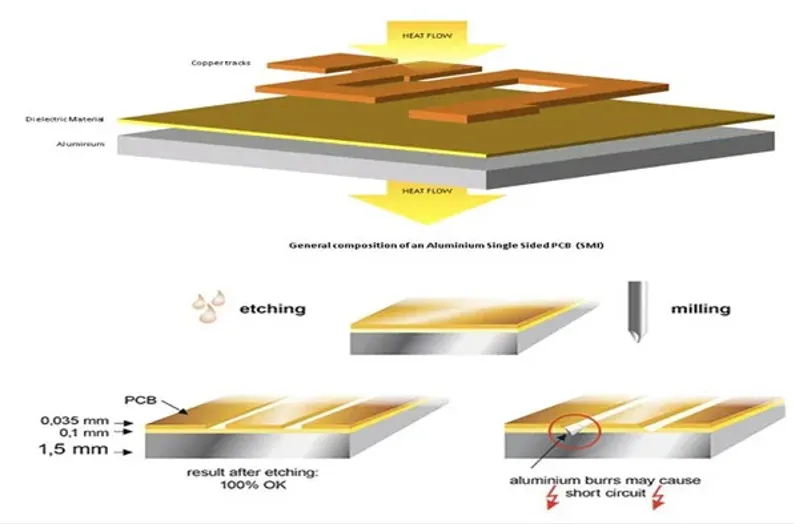
Aluminum PCBs consist of a copper circuit layer bonded to a thin thermally conductive dielectric, which sits on a thick aluminum base plate. This construction differs from standard FR4 boards by replacing the fiberglass core with metal for better heat transfer. In automotive PCB applications, they support high-power components like LEDs, MOSFETs, and IGBTs that generate significant heat. The aluminum core spreads heat evenly, preventing localized hotspots that could degrade solder joints or components. Manufacturers produce them in single or double-sided configurations, often with thicknesses tailored to specific thermal needs. Their relevance stems from automotive environments where temperatures swing from below freezing to over 125 degrees Celsius, demanding materials that maintain integrity.
Aluminum offers a thermal conductivity around 200 times higher than FR4, enabling direct heat sinking without additional spreads. This property directly addresses automotive PCB thermal stress by minimizing temperature gradients across the board. Vibration resistance improves due to the metal core's rigidity, which reduces flexing compared to flexible substrates. Engineers select aluminum PCBs for applications requiring compliance with performance specifications, ensuring reliability over the vehicle's lifecycle. Cost-effectiveness also plays a role, as they simplify assembly by integrating heat management into the board itself.
Technical Principles Behind Aluminum PCB Performance in Harsh Conditions
Heat dissipation in aluminum PCBs follows conduction principles, where the aluminum base acts as a heat sink, channeling thermal energy away from sensitive traces and components. The dielectric layer, typically ceramic-filled polymer, provides electrical isolation while maintaining high thermal transmittance, often exceeding 1 W/mK. During operation, power losses convert to heat, creating automotive PCB thermal stress that expands materials at different rates. Aluminum's coefficient of thermal expansion closely matches silicon in semiconductors, reducing shear stress on solder joints during cycles. This alignment prevents cracks, a common failure mode in standard boards.
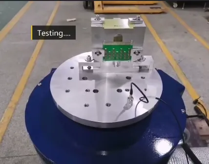
Vibration resistance arises from the aluminum core's high stiffness, which dampens mechanical energy and limits board deflection under dynamic loads. In automotive settings, engines and road conditions induce resonances that fatigue traditional laminates, leading to trace fractures. The metal backing distributes stress evenly, enhancing overall structural integrity. Testing per industry standards verifies this by simulating prolonged exposure to sinusoidal and random vibrations. Thermal management further bolsters reliability by keeping junction temperatures within safe limits, extending component lifetimes.
Finite element analysis reveals how aluminum PCBs minimize warpage from thermal mismatch. During reflow soldering or operation, uneven heating causes bowing in FR4, but the rigid base constrains it. Engineers model these effects to optimize trace routing and via placement for uniform heat flow. Compliance with qualification standards like IPC-6012 ensures boards withstand these stresses without delamination.
Addressing Automotive PCB Thermal Stress with Aluminum Substrates
Automotive PCB thermal stress originates from rapid temperature changes in underhood modules, where components cycle between idle cool-downs and peak loads. Aluminum PCBs mitigate this by providing a low-impedance thermal path to external heatsinks or chassis. Copper pours and embedded vias enhance spreading, directing heat laterally before vertical escape. This reduces peak temperatures by up to significant margins compared to organic boards, preserving reliability. Design guidelines from IPC-2221 emphasize plane sizing and material selection to balance electrical and thermal performance.
In electric vehicles, inverters and battery management systems push power densities higher, amplifying stress. Aluminum cores handle these by coupling directly to cooling fins, bypassing intermediate layers. Humidity resistance improves as the metal base resists moisture ingress better than porous laminates. Combined, these features ensure stable operation across the full automotive temperature range. Practical implementation involves specifying dielectric thickness to trade off voltage standoff against conductivity.
Enhancing Automotive PCB Vibration Resistance
Vibration in vehicles comes from engine harmonics, tire impacts, and suspension movements, testing board durability. Aluminum PCBs excel in automotive PCB vibration resistance due to their high Young's modulus, which resists deformation. The core absorbs energy, protecting surface-mount parts from g-forces that could shear leads. Standards like ISO 16750-3 outline mechanical load tests, including broad-band random vibration up to 2000 Hz, which aluminum designs pass with minimal degradation.
Trace routing perpendicular to vibration axes minimizes fatigue, while the metal plane anchors anchors. Solder joint reliability improves as the substrate remains flat, avoiding pump-out during cycles. In power electronics, where heavy components mount, this stability prevents microcracks. Field data shows aluminum boards outlasting FR4 in shaker tests simulating years of service.
Best Practices for Aluminum PCB Reliability in Automotive Design and Manufacturing
Start with stackup optimization, ensuring symmetric copper builds around the core to prevent bow. Select dielectrics with proven CTE matching to aluminum, around 20-25 ppm/C. Incorporate thermal vias under hot components, filled for reliability, and wide planes for spreading. Adhere to IPC-2221 for spacing and current carrying capacity under elevated temperatures. During manufacturing, control lamination pressure to avoid voids in the dielectric bond.
Assembly requires low-stress soldering profiles to match the board's thermal mass. Post-process with conformal coatings for corrosion protection in salty road environments. Qualification involves thermal cycling and vibration per relevant standards, verifying no opens or shorts. Procurement specs should mandate traceability and process controls aligned with quality systems. These steps ensure aluminum PCB reliability across production volumes.
Key Applications and Insights from Automotive Deployments
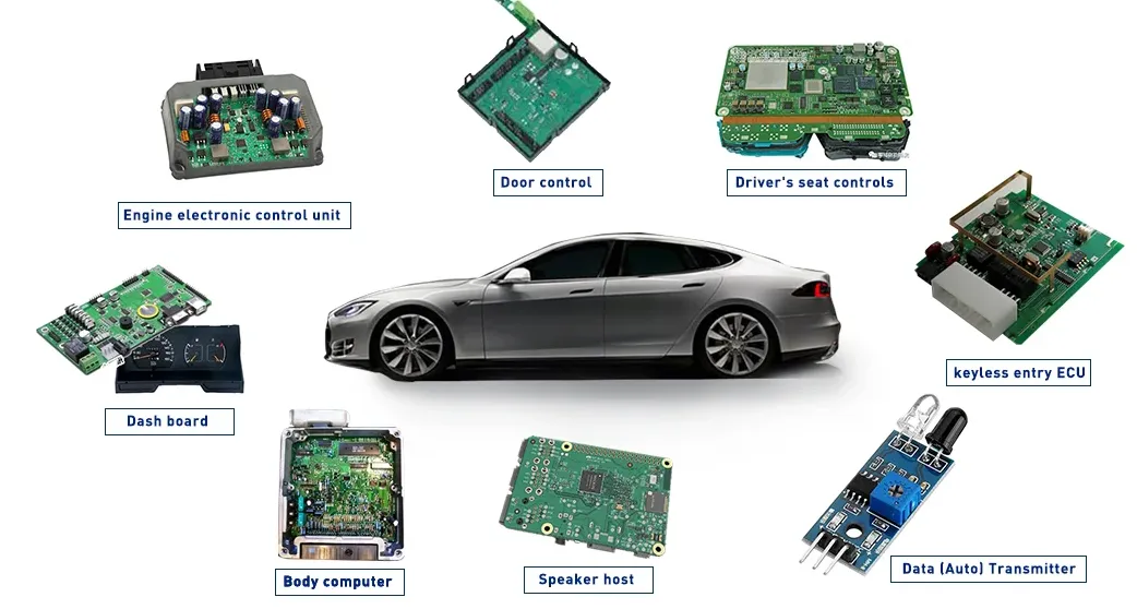
In headlamp systems, aluminum PCBs manage LED driver heat, maintaining lumen output over time. Engine control units benefit from vibration damping, reducing intermittent faults. Electric drivetrains use them for gate drivers and sensors near motors. Troubleshooting common issues like dielectric breakdown involves checking bond integrity via cross-sectioning. Insights from deployments highlight the value of iterative thermal modeling early in design.
Conclusion
Aluminum PCBs play a critical role in automotive electronics by delivering unmatched thermal dissipation and mechanical robustness. They counter automotive PCB thermal stress and vibration through inherent material properties and smart design. Integrating them into applications ensures compliance with demanding environments. Engineers achieve higher reliability by following established practices and standards. As automotive systems evolve, aluminum substrates will remain essential for performance and safety.
FAQs
Q1: What makes aluminum PCB automotive applications superior for thermal management?
A1: Aluminum PCBs feature a metal core that conducts heat far better than FR4, spreading it quickly to sinks. This reduces automotive PCB thermal stress on components during high-load operation. Design with vias and planes optimizes flow, aligning with IPC-2221 guidelines. Reliability improves as temperatures stay controlled, preventing failures in engine bays or EV packs.
Q2: How do aluminum PCBs improve automotive PCB vibration resistance?
A2: The rigid aluminum base minimizes flexing under dynamic loads, protecting traces and joints. It dampens energy from road and engine vibrations effectively. Testing per ISO 16750-3 confirms endurance. This makes them suitable for ECUs and sensors in rough conditions.
Q3: What are common automotive PCB applications for aluminum boards?
A3: Key uses include power inverters, LED lighting, motor controls, and ADAS modules. They handle heat and vibration in these high-stress spots. Aluminum PCB reliability supports electrification trends without added cooling complexity.
Q4: Why prioritize aluminum PCB reliability in harsh automotive environments?
A4: Harsh conditions like thermal cycling and moisture degrade standard boards faster. Aluminum's properties extend service life, meeting qualification standards. It simplifies designs while ensuring consistent performance.
References
IPC-2221C — Generic Standard on Printed Board Design. IPC, 2023
ISO 16750-3:2023 — Road vehicles - Environmental conditions and testing for electrical and electronic equipment - Part 3: Mechanical loads. ISO, 2023
IPC J-STD-001J — Requirements for Soldered Electrical and Electronic Assemblies. IPC, 2024
IPC-6012DS — Qualification and Performance Specification for Rigid Printed Boards. IPC, 2016





