 ALLPCB


Introduction
Rigid-flex printed circuit boards, often called flex-to-rigid PCBs, integrate rigid substrates with flexible circuits to enable compact, reliable designs in demanding environments. These hybrid boards have evolved from niche solutions to essential components in modern electronics, driven by the need for space savings and mechanical adaptability. As electronic devices shrink and become more dynamic, the future of rigid-flex PCBs promises innovations that address miniaturization, high-speed signaling, and harsh operating conditions. Engineers must understand these developments to harness trends in flex PCB technology for next-generation products. This article explores emerging rigid-flex applications, key advancements, and practical considerations aligned with industry manufacturing practices.
Adoption accelerates as devices integrate more functions into smaller footprints, positioning rigid-flex as a cornerstone for future electronics. Manufacturers focus on scalability, ensuring these boards meet performance specs under repeated flexing.
Understanding Rigid-Flex PCBs and Their Growing Relevance
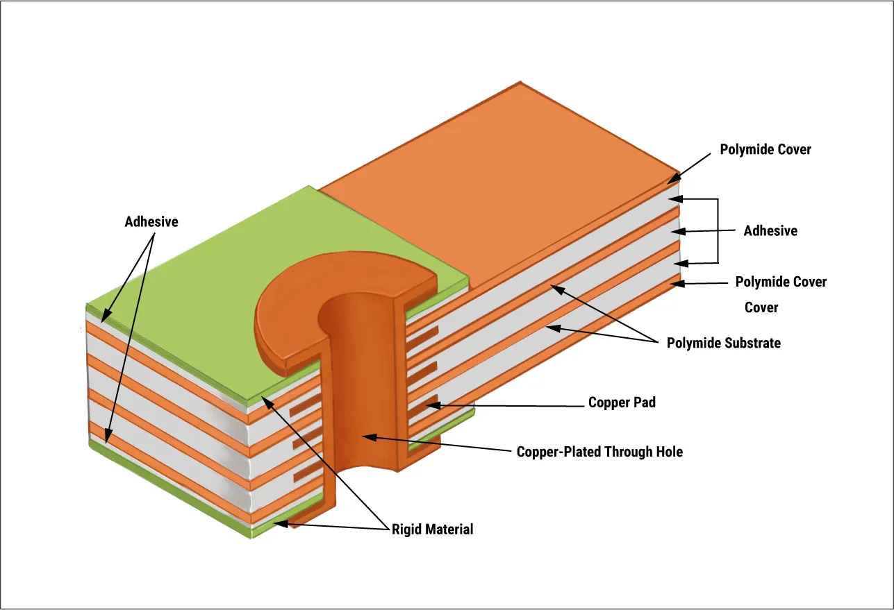
Rigid-flex PCBs combine the structural integrity of rigid boards with the bendability of flexible polyimide-based circuits, allowing seamless transitions between sections without connectors. This design reduces assembly points, minimizes weight, and enhances reliability in folded or curved assemblies. In manufacturing, the rigid sections host high-density components while flex areas route signals through dynamic bends, making them ideal for applications where traditional rigid boards fail due to size constraints. The relevance stems from rising demands in sectors like consumer electronics and automotive systems, where space and vibration resistance are critical. Factory processes emphasize precise lamination of rigid cores with flex layers to ensure interlayer adhesion and signal integrity.
Adoption accelerates as devices integrate more functions into smaller footprints, positioning rigid-flex as a cornerstone for future electronics. Manufacturers focus on scalability, ensuring these boards meet performance specs under repeated flexing.
Emerging Trends in Flex PCB Technology
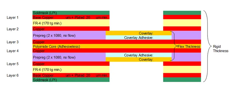
Trends in flex PCB technology center on achieving finer line widths, higher layer counts, and improved material properties to support high-frequency signals up to millimeter-wave bands. Advances include high-density interconnects (HDI) structures embedded in flex sections, enabling via-in-pad and microvias for denser routing. Polyimide films with enhanced thermal stability allow operation in extreme temperatures, while thinner copper foils reduce signal loss in bends. Manufacturing shifts toward sequential lamination, where rigid and flex sections build incrementally to control warpage. These developments pave the way for the future of rigid-flex PCBs by supporting integration with active components directly on flex areas.
Another key trend involves sustainable materials, such as recyclable adhesives and low-halogen dielectrics, to align with environmental regulations without compromising flex endurance. Factories optimize laser drilling and plasma etching for precise flex circuit patterning, boosting yield rates.
Hybrid constructions now incorporate embedded resistors and capacitors in rigid zones, transitioning smoothly to flex tails for connectors. This evolution addresses signal integrity challenges in high-speed designs.
Driving Rigid-Flex PCB Innovation Through Materials and Processes
Rigid-flex PCB innovation hinges on advanced coverlays and stiffeners that protect flex circuits during repeated bending cycles. New adhesive systems provide stronger bonds between rigid FR-4 cores and flex polyimide, preventing delamination under thermal cycling. Processes like controlled impedance flex routing ensure consistent performance across bends, critical for RF applications. Factories employ automated optical inspection for flex alignment during lamination, reducing defects in multilayer builds. Per IPC-6013DS, Qualification and Performance Specification for Flexible and Rigid-Flex Printed Boards, these boards undergo rigorous flex endurance and thermal shock testing to validate reliability.
Innovations extend to blind and buried vias that span rigid-flex transitions, maximizing routing density. Manufacturing tolerances tighten to 50-micron lines in flex areas, supporting 5G and beyond.
Scalable production techniques, including panel-level processing, lower costs for high-volume runs while maintaining precision.
Emerging Rigid-Flex Applications Across Industries
Emerging rigid-flex applications span wearables, where thin flex tails connect sensors to rigid processing units in smartwatches and fitness trackers. In medical devices, these boards enable implantable pacemakers and endoscopes, folding to fit tiny anatomies while withstanding bodily fluids and sterilization. Automotive sectors leverage rigid-flex for advanced driver-assistance systems (ADAS), routing cameras and lidars through curved dashboards with vibration resistance. Aerospace uses them in satellites for lightweight interconnects that endure launch stresses and thermal vacuums.
Consumer foldable displays rely on rigid-flex hinges that flex millions of cycles without cracking. In robotics, they form articulated joints, combining rigid motor mounts with flexible sensor harnesses.

Industrial IoT sensors deploy rigid-flex for harsh environments, integrating rigid power sections with flex for conformal mounting.
Challenges in Manufacturing Future Rigid-Flex PCBs and Best Practices
Manufacturing rigid-flex PCBs faces challenges like warpage from mismatched CTE between rigid and flex materials, addressed through symmetric stackups and low-stress adhesives. Flex section cracking during bending requires optimized bend radii per design guidelines. Factories implement strain-relief features, such as teardrop pads, to distribute mechanical stress. IPC-2223B, Sectional Design Standard for Flexible/Rigid-Flexible Printed Boards, guides bend zone layouts to prevent copper fatigue. Best practices include simulation of dynamic flexing early in design to predict failure points.
Quality control emphasizes cross-section analysis post-lamination to verify adhesion and void-free bonds. Thermal profiling during soldering prevents flex damage, using low-temperature alloys where possible.
Procurement teams should specify flex cycles and environmental quals upfront to align with factory capabilities.
Conclusion
The future of rigid-flex PCBs lies in their ability to enable compact, resilient electronics through trends in flex PCB technology and rigid-flex PCB innovation. From HDI integration to advanced materials, these boards meet demands of emerging rigid-flex applications in medical, automotive, and consumer sectors. Factory-driven insights underscore adherence to standards for reliable production. Engineers adopting these advancements will design systems that outperform traditional rigid boards in dynamic environments. Staying informed on these evolutions ensures competitive edge in PCB development.
FAQs
Q1: What are the main trends in flex PCB technology shaping the future of rigid-flex PCBs?
A1: Trends focus on miniaturization with HDI vias, advanced polyimide materials for higher thermal endurance, and sustainable dielectrics. Manufacturing emphasizes precise lamination to handle finer pitches and high-layer counts. These align with demands for high-speed signals in compact devices, per IPC guidelines. Factory processes optimize for yield in multilayer flex-rigid hybrids.
Q2: How do emerging rigid-flex applications benefit from hybrid designs?
A2: Hybrid rigid-flex designs save space by eliminating connectors, ideal for wearables and foldables. They withstand vibrations in automotive ADAS and thermal extremes in aerospace. Reliability improves through integrated routing, reducing failure points. Manufacturers ensure performance via bend testing and adhesion checks.
Q3: What role do industry standards play in rigid-flex PCB innovation?
A3: Standards like IPC-6013DS define qualification tests for flex endurance and electrical performance. They guide material selection and process controls to prevent delamination. Innovation builds on these for consistent manufacturing of high-density boards. Compliance ensures suitability for critical applications.
Q4: What best practices ensure reliable future rigid-flex PCBs?
A4: Use symmetric stackups to minimize warpage, optimize bend radii per IPC-2223B, and simulate mechanical stress. Select CTE-matched materials and inspect interlayer bonds. Factories recommend sequential build-ups for complex layers. These practices support long-term reliability in dynamic uses.


