Overview
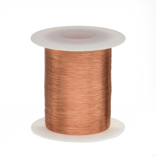
Conventional thermostats use separate temperature sensors and heater elements with a feedback loop between them. Recent design ideas have combined sensor and heater functions into a single active device (typically a FET or BJT). This article follows that fusion concept but uses fine-specification copper wire (for example 40 AWG polyurethane-insulated wire) as an integrated temperature sensor and heater.
Principle
The miniature thermostat uses the temperature coefficient of 40 AWG copper and I^2R self-heating as the combined sensor/heater.
Standard 40 AWG copper has a resistance and temperature coefficient at 25 C typically about 1.07 ohm/ft and +0.393%/C, respectively. Therefore, the resistance of an L-foot length of 40 AWG at a given temperature T is approximated by:
R(L,T) = 1.07 L (1 + 0.00393 (T - 25))
Expanded:
R = 1.07 L + 0.00421 L T - 0.00421 L 25
Solved for T:
T = (R - 1.07 L + 0.00421 L 25) / (0.00421 L)
Or simplified:
T = (R - 0.965 L) / (0.00421 L)
Formula above applies from R/L = 0.965 ohm/ft at 0 C to 1.6 ohm/ft at 155 C (the suggested upper temperature for solderable polyurethane-insulated wire).
Using the Wire as Sensor and Heater
If a suitable length (5 to 15 ft) of wire is placed in the feedback loop and driven with current sufficient to dissipate enough I^2R heat to raise and hold the wire at a preset resistance, the temperature of the wire—and any thermally coupled load—will also be held at that temperature. That is the function of the circuit described here.
Q1's drain provides heating. The heating current through the sensor/heater wire is I (temporarily ignoring the small contribution of the start-up resistor R2). The voltage across the wire resistance R is:
V = I R
This causes A1b and current source Q2 to produce an output:
I2 = V / (R4 + R7) = I R / (R4 + R7)
At pin 2 of A1b the induced voltage is:
V2 = I2 (R5 + R6) = I R (R5 + R6) / (R4 + R7)
Meanwhile, Q1's source current (which is also equal to I) sampled by sense resistor R1 produces:
V3 = I R1
The FET-driver amplifier A1a forces the FET gate voltage to drive the wire current such that:
V2 = V3
Thus:
I R (R5 + R6) / (R4 + R7) = R1 I
And therefore the wire resistance is forced to the ratio set by the resistors:
R = R1 (R4 + R7) / (R5 + R6)
Accordingly, the heater current and the wire resistance and temperature are driven to a steady value determined purely by the resistor ratio in the equation above, and the final constant temperature is given by the temperature-resistance relation previously shown.
Q3 Protection
Regarding Q3: the thermostat circuit is designed to be flexible with respect to wire gauge, length and the resulting sensor/heater resistance. To accommodate situations where R < 10 ohm and the resulting potentially damaging peak currents, Q3 removes the gate drive to Q1 when necessary and limits I to a safe approximately 1.4 A.
Setup and Calibration
To accommodate various wire lengths and initial resistances, use this simple calibration procedure when replacing the wire.
- Before first power-up, let the sensor/heater wire reach ambient room temperature.
- Set R4 and R5 fully counterclockwise.
- Press and hold the CAL NC button.
- Apply power.
- Slowly turn R4 clockwise until the LED first flashes.
- Release CAL.
R5 is now calibrated to provide reasonable coverage from ambient up to 130 C across its CCW to CW range.
Mounting and Thermal Coupling
Thermal coupling between a chosen length of sensor/heater wire and the intended thermal load (for example thermostat circuit components, test tubes, Petri dishes, etc.) can be accomplished by winding the wire in a serpentine pattern around the load and securing it with polyimide tape, RTV silicone, or similar high-temperature adhesives.
 ALLPCB


