 ALLPCB


Introduction
Stencil printing equipment forms the foundation of surface-mount technology (SMT) processes in PCB assembly, especially for electronic hobbyists building custom boards at home. This setup allows you to apply solder paste accurately onto PCB pads before placing components, ensuring reliable solder joints without advanced machinery. Hobbyists often start with manual tools that deliver professional results on small batches, making it accessible for prototyping gadgets or repairs. Understanding the basics of stencil printing equipment helps avoid common pitfalls like bridging or insufficient paste volume, which can derail your project. In this guide, we cover the essential components, setup tips, and troubleshooting for hobbyist electronics enthusiasts ready to tackle PCB assembly.
What Is Stencil Printing Equipment?
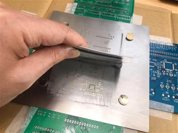
Stencil printing equipment refers to the tools and materials used to deposit solder paste through a thin metal stencil onto a PCB's surface pads. The core idea involves aligning a stencil frame over the bare PCB, then using a squeegee to push solder paste across the stencil's apertures, which match the pad layout. For hobbyist electronics, this equipment typically includes a reusable stencil, a manual printer frame or jig, squeegees, and solder paste dispensers. These components work together to create uniform paste deposits critical for subsequent reflow soldering. Unlike automated systems in factories, hobbyist versions prioritize simplicity and low cost while maintaining precision for fine-pitch components.
The stencil itself is a stainless steel sheet with laser-cut or chemically etched openings that act as a mask. Squeegees, often made from polyurethane or metal, sweep the paste evenly, preventing smearing. Solder paste, a mixture of flux and tiny solder spheres, fills these openings via capillary action and surface tension. Proper equipment selection ensures compliance with basic industry practices, setting the stage for successful PCB assembly runs.
Why Stencil Printing Matters for Hobbyist Electronics
In PCB assembly, stencil printing directly impacts joint quality, yield, and rework time, making it indispensable for hobbyists scaling from hand-soldering to SMT. Manual methods with stencil printing equipment reduce errors compared to syringe application, offering consistent volume control for components down to 0201 sizes. This precision minimizes defects like tombstoning or voids during reflow, common frustrations in hobbyist projects. For those prototyping IoT devices or wearables, reliable paste deposition speeds up iteration cycles without investing in pick-and-place machines.
Moreover, mastering stencil printing builds skills transferable to larger assemblies, aligning hobbyist workflows with professional standards. It promotes repeatability, essential when testing multiple board revisions. Poor printing leads to uneven heating in reflow ovens, causing failures that troubleshooting later proves time-consuming. By starting with the right stencil printing equipment, hobbyists achieve higher success rates, turning ambitious designs into functional electronics.
Key Components of Stencil Printing Equipment
Every stencil printing setup revolves around a few core items tailored for hobbyist electronics. The stencil is paramount, typically 0.1 to 0.15 mm thick for fine features, with apertures designed to release paste cleanly. Manual printer frames or jigs hold the stencil taut and allow precise PCB alignment using fiducials or edge clamps. Squeegees come in various durometers, with softer blades suiting irregular surfaces and harder ones for high-volume sweeps.
Solder paste requires storage in syringes or jars, selected for particle size matching your stencil apertures, such as Type 4 or 5 for hobbyist work. Alignment aids like transparent overlays or laser pointers ensure the stencil matches PCB pads within tight tolerances. Cleaning tools, including wipes, solvents, and under-stencil brushes, maintain equipment performance between prints. Together, these form a compact station fitting any workbench.
Technical Principles of Stencil Printing
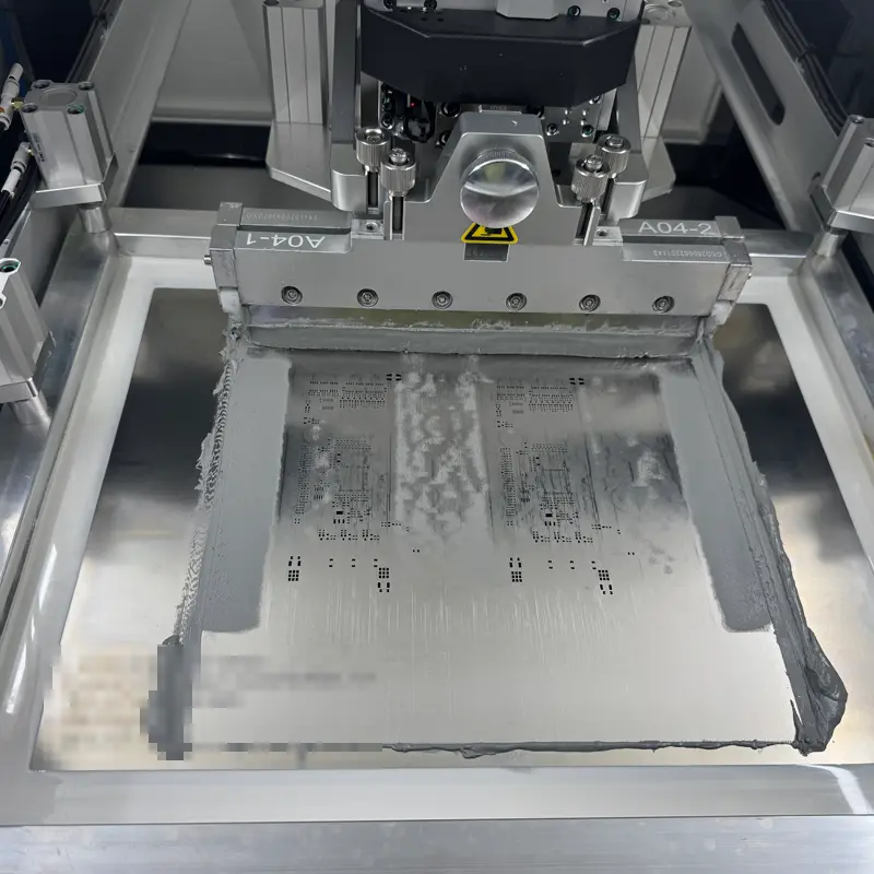
Stencil printing relies on the physics of rheology, where solder paste behaves as a thixotropic fluid, stiff under rest but flowing under shear from the squeegee. As the blade moves at controlled speed and pressure, paste fills apertures via squeegee-paste-board transfer, governed by surface tension and viscosity. Release occurs when the stencil lifts, with paste bridges snapping due to elasticity, leaving deposits 100-150% of pad area ideally. Factors like stencil thickness-to-aperture ratio influence volume; narrower walls prevent slumping.
Alignment precision, often under 50 microns for fine-pitch, prevents offset defects. Standards like IPC-7525 provide guidelines for aperture design, ensuring optimal paste transfer rates above 90%. Pressure from the squeegee, around 1-2 kg per blade length, balances fill without tunneling. Temperature control keeps paste workable, as colder material stiffens, risking incomplete deposits.
Gaps between stencil and PCB, known as gasket seal, must stay under 10% of thickness to avoid bridging. Flooding the stencil first coats apertures evenly before printing. These principles scale from hobbyist manual strokes to automated cycles, emphasizing consistent technique.
Setting Up Your Stencil Printing Equipment
Begin by securing your manual printer frame on a stable, level surface to minimize vibrations during sweeps. Cut or order stencils matching your Gerber files, verifying fiducial marks align with PCB edges. Apply a thin solder paste flood bar across the stencil top, then position the blank PCB underneath using clamps or vacuum hold-downs. Lower the stencil gently, checking parallelism with feeler gauges for uniform contact.
Select squeegees matching your stencil width; a 45-degree angle optimizes shear. Perform test prints on scrap boards, inspecting deposits under magnification for uniformity. Adjust angle, speed, and pressure iteratively, aiming for brick-like paste heights. Warm solder paste to room temperature for better flow, stirring to homogenize.
Cleaning protocols follow IPC-7526 recommendations, using lint-free wipes and isopropyl alcohol to remove residue without scratching apertures. Dry thoroughly to prevent oxidation. Store stencils flat, wrapped in anti-static bags. This setup yields dozens of prints per stencil, ideal for hobbyist batches.
Best Practices and Troubleshooting for PCB Assembly
Adopt a consistent printing stroke: flood, print left-to-right, lift stencil at 1-2 mm per second. Use dual squeegees for bidirectional printing on larger boards, halving cycle time. For hobbyist electronics, Type 4 solder paste suits most stencils, offering good release without clogging. Monitor environmental humidity below 60% to avoid paste drying.
Common issues include bridging, fixed by reducing gasket gap or using finer squeegees. Insufficient volume signals overly thin stencils or low pressure; increase blade downforce gradually. Smearing points to dirty stencils, resolved by thorough cleaning per IPC-7526. Tombstoning post-reflow traces back to uneven paste, so verify heights with a profilometer or caliper.
For multi-layer prototypes, print one side, inspect, then flip. J-STD-001 outlines acceptability criteria for paste deposits, guiding hobbyists toward reliable joints. Practice on varied board sizes builds intuition. Invest in a basic microscope for defect analysis, accelerating learning.
Conclusion
Stencil printing equipment empowers electronic hobbyists to achieve professional PCB assembly results with minimal investment. From stencils and squeegees to solder paste handling, each component plays a vital role in precision and efficiency. By following technical principles, setup best practices, and troubleshooting steps, you minimize defects and maximize yields. Standards like IPC-7525 and IPC-7526 ensure your methods align with industry expectations, even at home. Start small, iterate, and soon you'll handle complex SMT projects confidently, advancing your hobbyist electronics endeavors.
FAQs
Q1: What basic stencil printing equipment do I need for hobbyist PCB assembly?
A1: For hobbyist electronics, essential stencil printing equipment includes a stainless steel stencil, manual frame or jig, polyurethane squeegees, and Type 4 solder paste. Alignment tools like clamps and a microscope aid precision. This setup handles small batches reliably, applying uniform deposits for reflow. Follow IPC-7525 for aperture design to ensure clean release. Total cost stays under a few hundred dollars, perfect for prototyping.
Q2: How do I choose squeegees for solder paste printing in PCB assembly?
A2: Select squeegees based on durometer: 60-70 Shore A for general hobbyist use balances flexibility and durability. Match blade width to your longest aperture row for even pressure. Polyurethane resists wear better than metal for manual strokes. Angle at 45-60 degrees optimizes flow. Replace when edges bevel, preventing inconsistent solder paste transfer. Proper choice reduces defects like tunneling.
Q3: What are common troubleshooting tips for stencil printing equipment issues?
A3: Bridging often stems from excess paste or poor alignment; clean stencils and adjust gasket seal per IPC-7526. Low volume indicates insufficient pressure or cold solder paste, so warm to room temperature and increase downforce. Smearing requires fresher paste and lint-free wipes. Inspect deposits post-print for uniformity before component placement. Consistent technique resolves most hobbyist electronics challenges quickly.
Q4: Why is precise alignment critical in stencil printing for PCB assembly?
A4: Alignment ensures solder paste lands exactly on pads, preventing offsets that cause open joints or shorts during reflow. Use fiducials and transparent stencils for visual checks under 50 microns. Misalignment amplifies with fine-pitch parts common in hobbyist projects. J-STD-001 criteria demand centered deposits for joint integrity. Practice with jigs builds accuracy, boosting overall PCB assembly success.
References
[IPC-7525C — Stencil Design Guidelines. IPC, 2021]
[IPC-7526 — Stencil and Misprinted Board Cleaning Handbook. IPC]
[J-STD-001 — Requirements for Soldered Electrical and Electronic Assemblies. IPC]


