 ALLPCB


Introduction
Solder joint quality forms the foundation of reliable printed circuit board assemblies, where even minor imperfections can lead to failures in the field. The IPC-A-610 standard serves as the definitive reference for assessing acceptable solder joints, with particular emphasis on fillet formation across various component types. Engineers inspecting assemblies must understand solder fillet criteria to ensure mechanical integrity, electrical conductivity, and long-term durability. This guide delves into the practical aspects of IPC-A-610 solder joint evaluation, focusing on what constitutes acceptable fillets while highlighting common PCB soldering defects. By mastering these principles, technicians can troubleshoot issues effectively during production and inspection. Ultimately, adherence to these guidelines minimizes rework and enhances overall assembly performance.
Understanding Solder Fillets and Their Critical Role
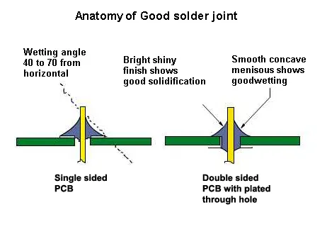
A solder fillet refers to the smooth, curved surface of solder that forms at the intersection of the component lead, pad, and board, providing visual evidence of proper wetting and metallurgical bonding. Well-formed fillets indicate complete reflow, adequate solder volume, and absence of contaminants, all essential for joint strength under thermal and mechanical stress. Poor fillets often signal underlying process issues like insufficient flux activation or improper temperature profiles, which compromise reliability in vibrating or high-temperature environments. In PCB assembly, fillets must meet specific shape and coverage requirements to pass visual inspection. Engineers rely on fillet appearance to gauge joint quality quickly, as it correlates directly with fatigue resistance and electrical performance. Ignoring fillet criteria risks field failures, making it a cornerstone of quality control.
IPC-A-610 Classes: Tailoring Criteria to Application Needs
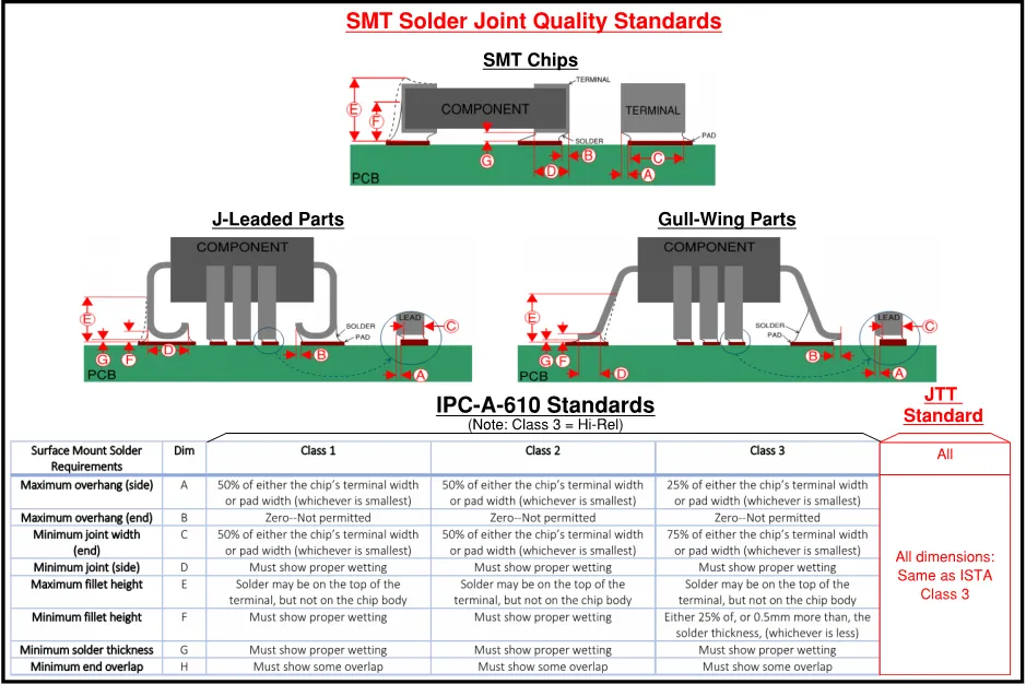
IPC-A-610 defines three product classes that dictate solder fillet acceptance levels, allowing flexibility based on end-use reliability demands. Class 1 suits general consumer electronics with basic criteria, while Class 2 targets dedicated service products like computers, requiring more robust fillets for extended life. Class 3 imposes the strictest standards for high-performance assemblies in aerospace or medical devices, demanding near-perfect wetting and fillet geometry. Fillet evaluation varies by class, with higher classes needing greater side joint lengths and heel fillet heights relative to lead dimensions. Technicians select the appropriate class per customer specifications to balance cost and performance. This classification ensures assemblies match their operational environment without over-engineering.
Through-Hole Solder Fillet Criteria Under IPC-A-610
For through-hole components, IPC-A-610 emphasizes vertical hole fill, barrel wetting, and external fillet formation to confirm a reliable intermetallic bond. Acceptable fillets appear concave and shiny, covering at least the specified percentage of the pad and lead surfaces without voids or cracks. Class 2 joints require substantial hole fill and visible fillets on both sides, while Class 3 demands complete fill and more extensive wetting. Fillets must rise smoothly from the pad edge without excessive solder that could bridge to adjacent pins. Insufficient fillet height often points to low solder volume or poor fluxing, leading to weak mechanical support. Inspectors check for 360-degree coverage where possible, ensuring the joint withstands shear forces.
Common measurements include minimum fillet heights at the heel and toe, scaled to component lead size. Overhang onto the board is limited to prevent shorts, and the fillet must not contact non-soldered package areas. In practice, angled views reveal wetting quality, with dull or grainy surfaces indicating cold joints. Troubleshooting starts with verifying lead protrusion through the board matches process controls. Proper clip length post-soldering preserves fillet integrity.
Surface Mount Solder Fillet Criteria for Key Component Types
Surface mount technology demands precise fillet control due to smaller geometries and reflow processes. For chip components like resistors and capacitors, IPC-A-610 requires end terminations to show smooth fillets with no end overhang and side joint lengths evidencing good pad coverage. Heel fillets must demonstrate wetting up the termination side, with maximum heights avoiding package body contact. Class 3 adds stricter side overhang limits and minimum joint widths for enhanced reliability. Defects like tombstoning disrupt fillet symmetry, often from uneven heating.
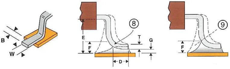
Gull-wing leads on SOICs and QFPs feature prominent heel and toe fillets, where the heel provides primary strength. Acceptable criteria include side joint length at least matching or exceeding lead width, with heel fillet height proportional to lead thickness plus solder layer. Toe overhang is controlled to fit pad dimensions, preventing electrical spacing violations. Class 2 allows moderate tolerances, but Class 3 mandates fuller coverage to resist vibration. Inspectors verify coplanarity affects fillet uniformity.
J-lead components under PLCCs follow similar rules, with fillets wrapping the lead curve for hidden joint visibility. Minimum heel fillet height ensures stress relief, while side overhang stays within pad bounds. These joints tolerate less deviation in higher classes due to fatigue sensitivity.
Identifying and Troubleshooting PCB Soldering Defects Related to Fillets
Many PCB soldering defects manifest as fillet anomalies, directly impacting IPC-A-610 compliance. Non-wetting shows as convex or beaded solder with angles exceeding acceptable limits, often from oxide layers or contaminated pads. Dewetting appears as solder pulling away post-reflow, leaving exposed base metal. Cold joints exhibit rough, matte fillets lacking shine, signaling interrupted reflow. Bridging connects adjacent pins via excess solder, while balls or beads pose shorts risks.
Solder inspection guides prioritize fillet shape: concave profiles indicate proper surface tension and alloy flow. Fractured or disturbed fillets suggest mechanical damage post-soldering. Lead-free alloys may show fillet lift or hot tears, acceptable if not excessive per class. Troubleshooting involves root cause analysis, like stencil misalignment causing uneven volume or profile spikes leading to insufficient melt. Rework focuses on flux cleaning and targeted reflow without damaging nearby joints.
Best Practices for Achieving Acceptable Solder Joints
Optimize stencil design for uniform paste deposition, matching aperture to pad size for consistent volume. Profile validation ensures peak temperatures promote wetting without overheating. Flux selection aids oxide removal, critical for fillet smoothness. Post-reflow, automated optical inspection flags fillet deviations early.
Operator training on IPC-A-610 visuals prevents human error. Cleanliness controls minimize defects like balls from flux residue. For mixed assemblies, sequence PTH before SMT to avoid disturbing fillets. Process indicators like slight projections guide adjustments without scrapping.
Conclusion
Mastering IPC-A-610 solder fillet criteria empowers engineers to produce robust assemblies free from common pitfalls. From through-hole fills to SMT heel heights, each aspect contributes to overall joint reliability. Regular inspection using these guidelines catches issues proactively, reducing downtime and costs. Apply class-specific tolerances to match product needs, always prioritizing wetting and smoothness. This approach ensures assemblies excel in demanding applications.
FAQs
Q1: What defines an acceptable IPC-A-610 solder joint fillet for Class 2 assemblies?
A1: Acceptable Class 2 fillets show smooth concave shapes with evidence of proper wetting on leads and pads, meeting minimum heel heights relative to lead and solder thickness. Side joint lengths cover adequate pad area without excessive overhang. No cracks, voids, or bridging occur, ensuring mechanical and electrical integrity. Inspectors verify these during visual checks to confirm reliability.
Q2: How do solder fillet criteria differ between Class 2 and Class 3 in IPC-A-610?
A2: Class 3 demands stricter tolerances, such as fuller hole fills for PTH and greater side joint coverage for SMT compared to Class 2. Heel fillet heights scale higher relative to lead dimensions, enhancing fatigue resistance. These elevate standards for high-reliability uses while Class 2 suffices for general service.
Q3: What are common PCB soldering defects affecting fillet quality?
A3: Defects include non-wetting with convex beads, cold joints showing rough textures, and bridging from excess solder. Dewetting exposes base metal, and insufficient volume yields low fillets. Address via process tweaks like flux optimization and temperature control for compliant joints.
Q4: How can engineers use a solder inspection guide based on IPC-A-610?
A4: Focus on fillet concavity, wetting angles under 90 degrees, and coverage proportions per component type. Cross-reference class requirements for heel and toe heights. Combine visual with X-ray for hidden joints to troubleshoot effectively.
References
IPC-A-610J — Acceptability of Electronic Assemblies. IPC, 2024
J-STD-001J — Requirements for Soldered Electrical and Electronic Assemblies. IPC, 2024


