 ALLPCB


Introduction
When designing printed circuit boards for modern electronics, engineers face a fundamental choice between surface mount technology (SMT) and through-hole technology (THT). This decision impacts board size, assembly efficiency, mechanical strength, and overall project viability. SMT enables compact designs with high component density, while THT provides robust connections suited to demanding environments. Understanding the trade-offs in SMT vs through-hole advantages, cost, and reliability helps optimize performance and avoid common pitfalls during prototyping and production. Factors like application requirements, volume, and environmental stresses guide the selection process. By evaluating these elements early, designers can prevent costly rework and ensure reliable operation.
What Is Surface Mount Technology (SMT)?
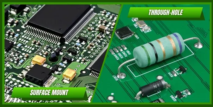
Surface mount technology involves placing components directly onto the surface of a PCB, where solder paste is applied to pads before reflow soldering. This method supports both sides of the board for mounting, allowing for significantly higher component density compared to traditional approaches. Engineers use stencils to deposit precise amounts of solder paste, followed by automated pick-and-place machines for component positioning. The assembly then enters a reflow oven, where controlled heating melts the paste to form reliable joints. SMT excels in applications requiring miniaturization, such as consumer devices and telecommunications equipment. Troubleshooting SMT issues often starts with verifying paste volume and oven profiles to avoid defects like tombstoning or bridging.
What Is Through-Hole Technology (THT)?
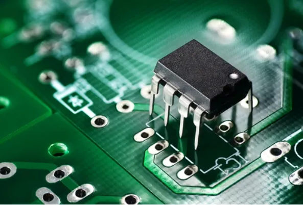
Through-hole technology requires components with leads that insert into drilled holes on the PCB, secured by solder on the opposite side. Assembly typically uses wave soldering, where the board passes over a molten solder wave, or selective soldering for complex boards. This technique provides strong mechanical bonds, making it ideal for components handling high currents or mechanical stress. Designers must account for hole sizes, annular ring dimensions, and lead tolerances to ensure proper fit and solder fill. THT remains common in power supplies, industrial controls, and legacy systems where repairability is key. Common troubleshooting involves checking for sufficient solder fillet and avoiding barrel cracks from excessive insertion force.
SMT vs Through-Hole Advantages
SMT offers key advantages in space efficiency and assembly speed, enabling double-sided population and finer pitch components. This results in smaller boards, reducing material costs and fitting tight enclosures. Automated processes minimize labor, supporting high-volume production with consistent quality. However, THT provides superior mechanical strength, as leads anchor components firmly against vibration and shock. THT joints distribute stress better across the full via barrel, enhancing durability in harsh conditions. Engineers often combine both in hybrid designs to leverage SMT density with THT robustness where needed.
In terms of signal integrity, SMT reduces parasitic inductance from shorter leads, improving high-frequency performance. THT suits lower-speed applications or those needing heat dissipation through larger components. SMT allows for better thermal management via ground planes under components, while THT excels with heatsinks on protruding leads. The choice hinges on balancing these SMT vs through-hole advantages against specific design constraints.
SMT vs Through-Hole Cost
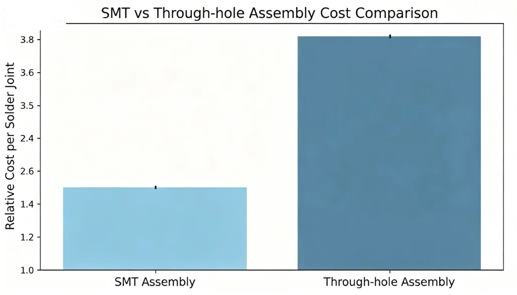
Cost differences in SMT vs through-hole cost arise primarily from assembly methods and economies of scale. SMT leverages automation, lowering per-unit labor in high volumes, though initial setup for stencils and programming adds expense. THT requires manual insertion or specialized fixtures, increasing costs for large runs but simplifying low-volume or prototype builds. Material savings from SMT's compact layouts offset higher precision drilling in THT. Engineers should model total cost of ownership, including rework rates and yield losses from assembly defects.
For mid-volume projects, SMT often proves more economical due to faster throughput and reduced handling. THT shines in scenarios with few high-power components, avoiding SMT's reflow challenges for large parts. Hidden costs like extended lead times for THT tooling versus SMT's standard processes influence budgeting. Practical tip: Prototype with THT for quick iterations, then transition to SMT for production to control SMT vs through-hole cost effectively.
SMT vs Through-Hole Reliability
Reliability comparisons in SMT vs through-hole reliability highlight environmental and mechanical factors. THT joints withstand higher vibration and thermal cycling due to greater solder volume and lead compliance. SMT relies on pad adhesion, vulnerable to pad cratering or component shift under stress. IPC-A-610J outlines acceptability criteria for both, classifying assemblies by end-use reliability levels. In high-vibration applications, THT reduces fatigue failures, while SMT performs well in controlled environments with proper underfill.
Thermal reliability favors THT for power components, as leads aid heat transfer away from the board. SMT mitigates this with via-in-pad designs but risks voiding under reflow. J-STD-001J specifies soldering requirements to ensure void-free joints, critical for long-term reliability. Troubleshooting reliability issues involves accelerated life testing, revealing weaknesses like THT barrel cracks or SMT head-in-pillow defects early.
Related Reading: Comparing Through-Hole vs. Surface Mount: Which Assembly Process is Right for You?
Best Practices for Choosing and Implementing SMT or THT
Start by assessing application demands: opt for SMT in space-constrained, high-speed designs and THT for mechanical robustness. Hybrid assemblies combine strengths, using THT for connectors and SMT for ICs. Follow IPC-7351B for SMT land patterns to optimize solder joint formation and prevent bridging. For THT, ensure via plating meets thickness requirements per IPC-6012 standards to avoid reliability gaps.
In assembly, validate processes against J-STD-001J for soldering parameters, adjusting profiles for mixed technologies. Perform design for manufacturability reviews, checking clearances and thermal loads. Use finite element analysis for stress-prone areas, simulating vibration to predict failures. Document inspections per IPC-A-610J classes, tailoring to product reliability needs.
Related Reading: Optimizing Mixed Technology PCB Assembly: A Guide to SMT and Through-Hole Integration
Applications and Troubleshooting Insights
In consumer electronics, SMT dominates for compact wearables, troubleshooting focused on reflow defects like insufficient wetting. Automotive modules blend both, with THT for sensors enduring shock. Aerospace favors THT or reinforced SMT for extreme reliability. Common pitfalls include mismatched thermal expansion in hybrids, addressed by CTE-matched materials. Vibration testing reveals THT superiority, while drop tests stress SMT adhesives.
Conclusion
Selecting between SMT and through-hole depends on balancing density, cost, and durability for your PCB design. SMT drives innovation in miniaturization and efficiency, while THT ensures rugged performance. Evaluate SMT vs through-hole cost, reliability, and advantages against project specifics for optimal results. Adhering to standards like IPC-A-610J and J-STD-001J minimizes risks. Hybrid approaches often provide the best of both, tailored to engineering needs.
FAQs
Q1: What are the primary SMT vs through-hole cost differences?
A1: SMT reduces costs through automation and compact boards in high volumes, while THT incurs higher labor for insertion but suits low-volume prototypes. Setup expenses for SMT stencils offset initial savings in small runs. Total cost includes yield and rework, favoring SMT for scale. Engineers model volumes to decide, avoiding overcommitment to one method.
Q2: How does SMT vs through-hole reliability compare in vibration environments?
A2: THT offers better reliability via mechanical anchoring, resisting fatigue better than SMT's surface bonds. IPC-A-610J criteria guide joint inspections for both. SMT improves with underfill, but THT handles shocks natively. Test under real conditions to validate choices.
Q3: What are the main SMT vs through-hole advantages for high-density designs?
A3: SMT enables finer pitches and double-sided assembly, maximizing density over THT's hole constraints. It supports high-speed signals with low inductance. THT advantages lie in strength, not compactness. Hybrids leverage both for balanced designs.
Q4: When should electric engineers prefer THT over SMT?
A4: Choose THT for high-power, high-vibration, or repair-heavy applications where mechanical strength trumps density. J-STD-001J ensures robust soldering. SMT fits most modern compact needs. Assess environment first.
References
IPC-A-610J — Acceptability of Electronic Assemblies. IPC, 2024
IPC J-STD-001J — Requirements for Soldered Electrical and Electronic Assemblies. IPC, 2024
IPC-7351B — Generic Requirements for Surface Mount Design and Land Pattern Standard. IPC, 2010


