ALLPCB


Overview
Addressing limitations of previous electronic blood pressure monitors, this article introduces a design for a smart electronic blood pressure monitor based on a programmable system-on-chip (SOPC). The blood pressure measurement method uses an inflation-based oscillometric technique. The system uses Cyclone II series low-cost FPGA and an embedded Nios II soft core as the main processor, and supports automatic blood pressure measurement, information display, data storage, and viewing and deletion of historical data. Using an FPGA simplifies circuit design, improves system reliability and stability, and gives the system strong extensibility for future upgrades.
Blood pressure is an important physiological parameter reflecting the state of the cardiovascular system. Appropriate blood pressure is necessary to maintain normal metabolism. With rising living standards and an aging population in urban areas, self-health awareness has increased. Electronic blood pressure monitors offer low cost, compact size, and high automation, and are widely used in households. SOPC (system-on-a-programmable-chip) is a flexible, efficient SoC solution proposed by Altera. Using programmable logic technology to place the entire system on a single chip, SOPC can integrate MCU, DSP, and FPGA functions.
1. Principles of Blood Pressure Measurement
1.1 Oscillometric measurement during inflation
There are several blood pressure measurement methods; the most common noninvasive methods are the Korotkoff sound method and the oscillometric method. This design uses the inflation-based oscillometric method. Inflation-based oscillometric measurement is essentially the reverse process of deflation-based measurement. During pressure increase (inflation), the system detects the static cuff pressure and oscillations of the gas inside the cuff. These oscillations originate from arterial wall pulsation. When cuff pressure is low and still below diastolic pressure Pd, the arterial wall is fully expanded during diastole and wall stiffness is higher, so oscillation amplitude remains small. As cuff pressure increases and rises above systolic pressure Ps, the artery is occluded and only small oscillations are present due to proximal pulse impact. When cuff static pressure equals the mean arterial pressure, the oscillation amplitude reaches a maximum. The envelope of the oscillations and the corresponding cuff static pressure indirectly reflect arterial blood pressure.
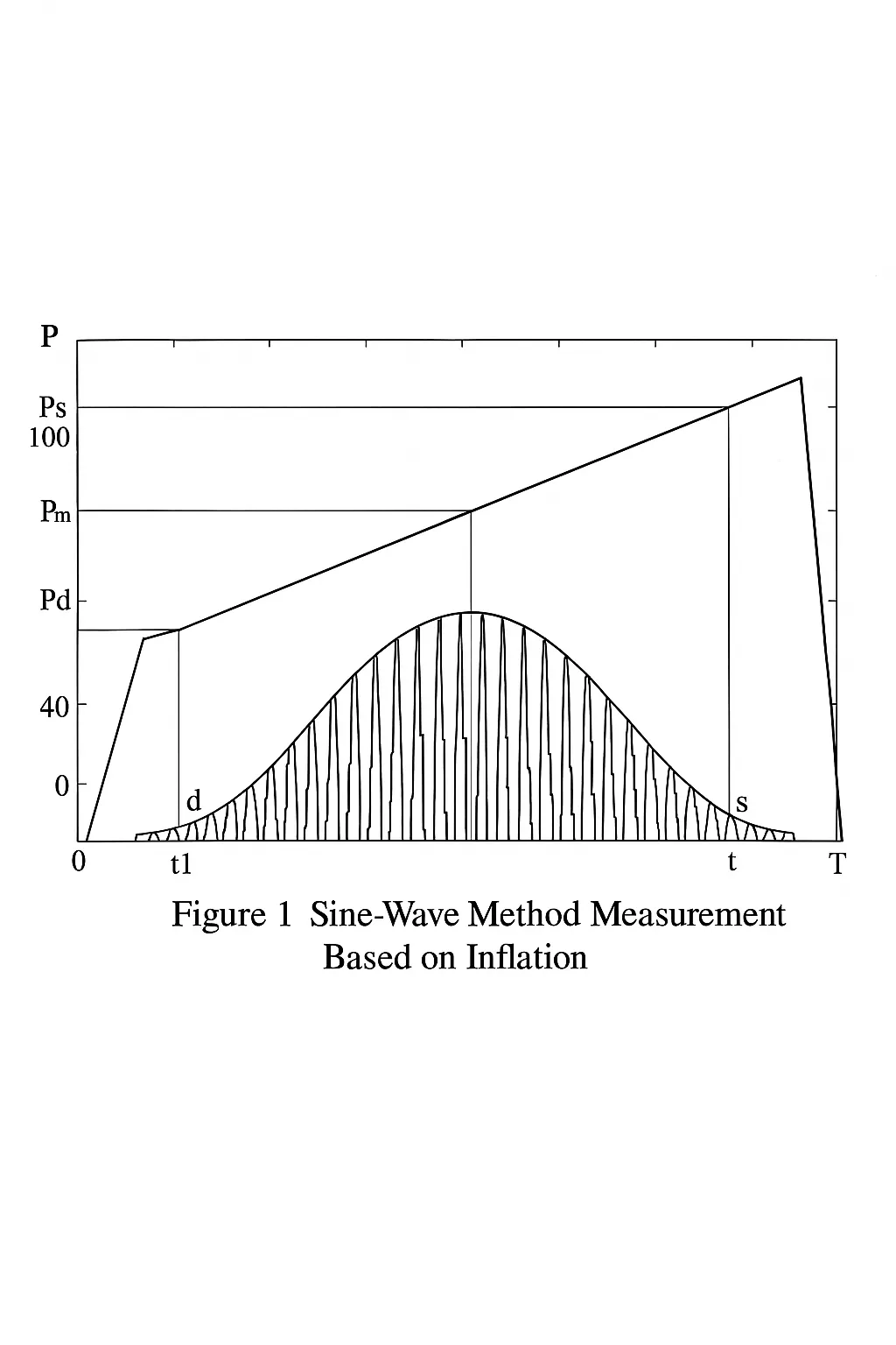
1.2 Heart rate calculation
Heart rate is the number of heartbeats per minute. Because heartbeats correspond to pulse waves, heart rate can be obtained during blood pressure measurement. Heart rate determination relies on detecting pulse-wave peaks and counting how many pulse waves occur within a given time window to calculate beats per minute.
2. SOPC System Hardware Design
2.1 SOPC system circuit
This section of the circuit consists of the FPGA chip, memory, and other peripheral components and forms the core of signal processing. Using the SOPC Builder hardware development environment, an embedded microprocessor system including CPU, memory interface, and I/O peripherals is constructed. After completing the system design, SOPC Builder generates the system. The following shows the system configuration built in SOPC Builder.
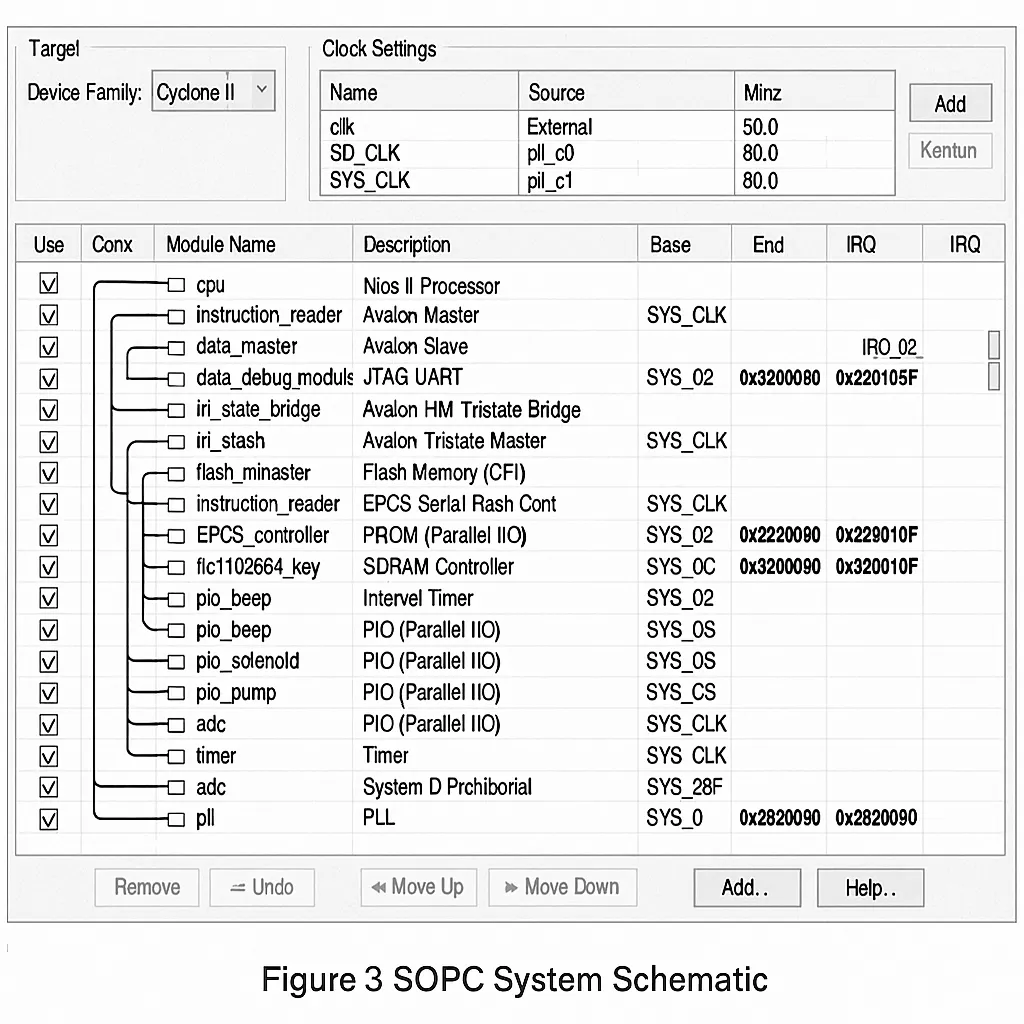
An EPCS device controller core is added to the SOPC system to make efficient use of system resources by storing FPGA configuration data and the Nios II software program in the EPCS chip, leaving more flash space available for storing measurement results. The Nios II processor reset address is set to the base address of the EPCS controller; after system reset, the program stored in EPCS is automatically downloaded to SDRAM for execution.
2.2 Pressure measurement circuit
2.2.1 Pressure sensor selection
The design uses the Motorola MPXV5050GP pressure sensor. It contains an internal signal amplifier and conditioning, offers good linearity, and directly converts arterial pressure on the vessel wall into an electrical signal of 0.2-4.7 V corresponding to 0-375 mmHg, which matches the design requirements of the blood pressure monitor.
2.2.2 Driver circuit design
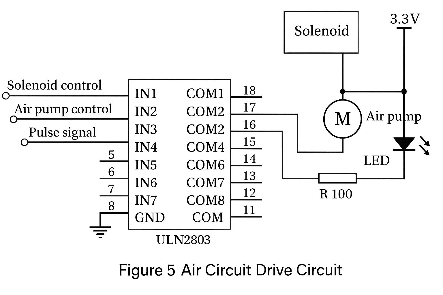
Control signals for the air pump and solenoid valve are generated by the FPGA. The pump requires a drive current of 450 mA and the solenoid valve requires 75 mA, which exceed the output capability of FPGA digital I/O. To provide the required drive current, a ULN2803 Darlington transistor array driver is used to drive the pump and valve. The ULN2803 can handle up to 500 mA; in this design, channel 1 drives the solenoid valve, channel 2 drives the pump, and channel 3 drives an LED to indicate pulse-wave signals, as shown below.