ALLPCB


Overview
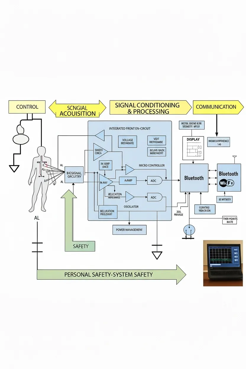
In many higher-level systems and patient monitoring devices, data acquisition systems follow a common signal chain: signal acquisition, signal conditioning and processing, and communication. Deeper inspection reveals several design issues to consider, such as the effects of signal integrity and common-mode rejection. Ensuring patient safety when using electrical connections is also critical, and it increases design complexity. Patients may require defibrillation at times, and the system must be protected from such events. In addition, various industry standards and practical considerations affect the final system design.
Figure 1 shows a typical signal chain for a 12-lead ECG monitor. The architecture can be complex and contains many subtle variations.
ECG monitoring
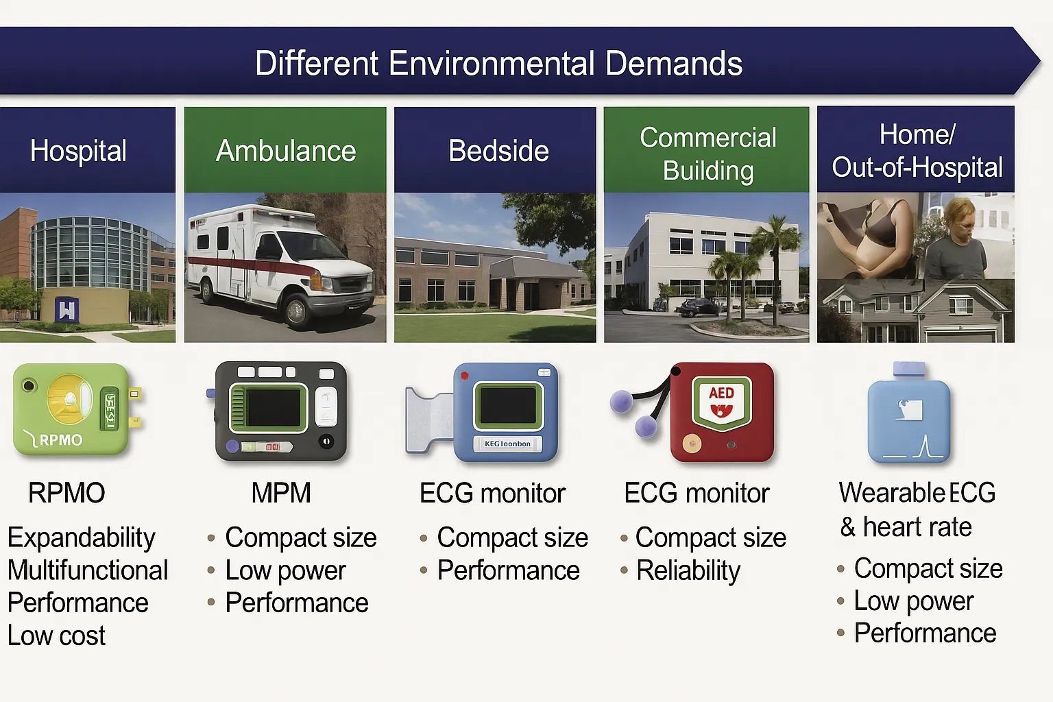
ECG measures the heart's electrical activity. Devices that measure ECG include portable Holter monitors, clinical electrocardiographs, and high-channel cardiac mapping systems. These systems are developed for a wide range of environments. Typical clinical settings include operating rooms, intensive care units, and electrophysiology labs, each with its own design challenges. As healthcare moves toward remote patient monitoring, developers face new challenges that require updated technical approaches.
ECG signals
An ECG is a noninvasive recording of the heart's electrical activity as seen on the body surface via skin electrodes. Typical ECG amplitudes range from about 0.25 mV to 5 mV and consist of multiple waveform components representing normal sinus rhythm or deviations from it. Deviations from normal sinus rhythm may indicate pathology that clinicians can evaluate and act on.
ECG waveform components
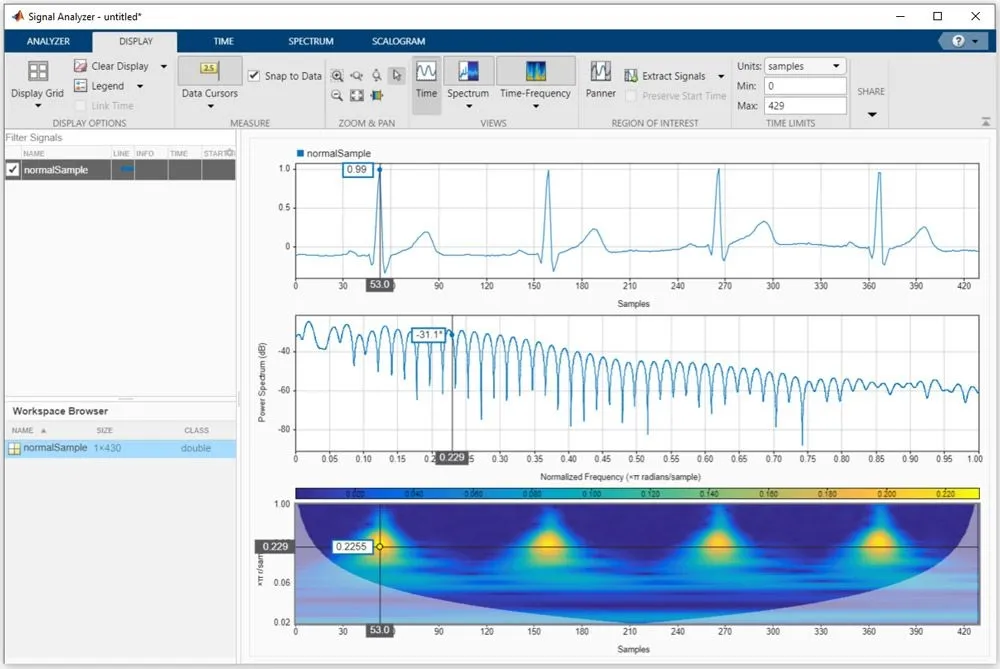
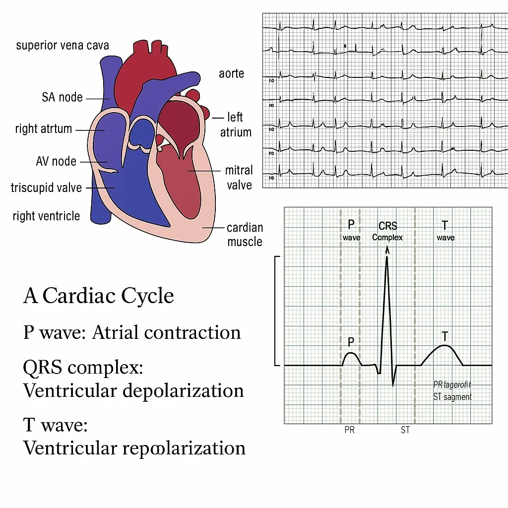
The ECG waveform includes the P wave, the QRS complex, and the T wave, which together represent one cardiac cycle. P wave corresponds to atrial depolarization. The QRS complex corresponds to ventricular depolarization. The T wave represents ventricular repolarization following depolarization. By analyzing electrical characteristics at different levels of the heart, clinicians can identify many functional abnormalities.
ECG measurement and lead systems
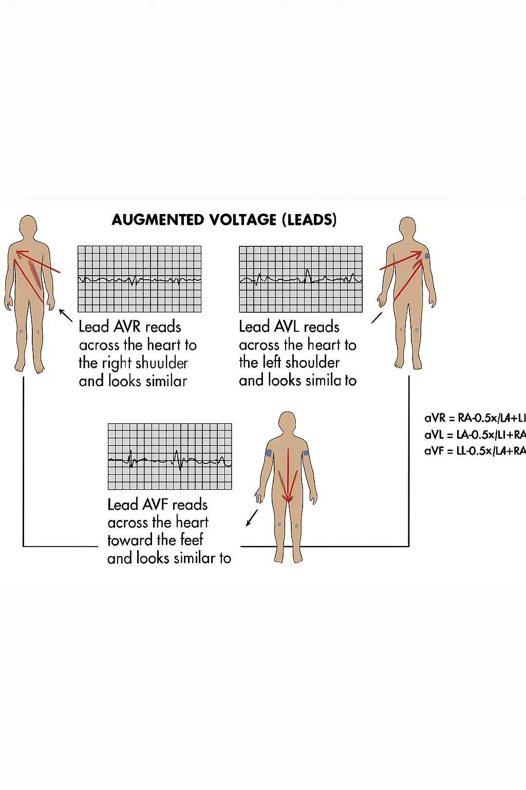
In ECG measurement, electrodes act as potential sensors and are placed on the chest and/or limbs. Leads are mathematical combinations of electrode potentials. For historical reasons, the 12-lead ECG remains the most common clinical configuration. The 12-lead ECG includes three standard limb leads based on the right arm, left arm, and left leg, known as the Einthoven leads. There are also three augmented limb leads, aVR, aVL, and aVF, commonly referred to as the Goldberger augmented leads, and six precordial leads, V1 through V6. The precordial leads, or V leads, are typically considered independent vectors. The Wilson central terminal and the target V electrode differ in reference; the Wilson central terminal itself is formed from the right arm, left arm, and left leg leads and serves as a three-way reference. To obtain a 12-lead ECG, nine electrodes are sufficient. A tenth electrode is often used to provide the right-leg drive. Mapping additional cardiac regions increases the complexity of measuring cardiac bioelectric signals.
Lead relationships
Like the Einthoven leads, the augmented limb leads can be viewed as independent vectors. The signals for leads I, II, and III are measured between the two arms or between one arm and the left leg. The augmented leads aVL, aVR, and aVF derive from the same three electrodes as leads I, II, and III. For example, aVL has the left arm as the positive electrode and a combination of the right arm and right leg as the negative electrode. Thus, these augmented leads are not independent of the standard limb leads. The chest leads V1 through V6 place six positive electrodes on the chest, with the Wilson central terminal serving as the reference or negative electrode for these measurements.