 ALLPCB


Home automation projects often begin with simple infrared remote controls that allow users to operate lights, fans, and other appliances from a distance. A CEM-1 PCB provides an economical foundation for these circuits because it supports single-sided construction suitable for low-complexity designs. Hobbyists appreciate the material for its balance of cost and performance in DIY remote control applications. The approach reduces the need for complex multilayer boards while maintaining reliable signal transmission in typical household environments. This combination makes CEM-1 PCB remote control design accessible for electronic enthusiasts seeking practical home automation solutions.
What Is a CEM-1 PCB and Why It Matters for Remote Controls
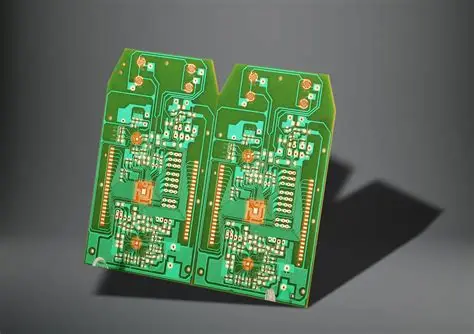
CEM-1 is a composite epoxy material commonly used for single-sided printed circuit boards. It consists of a paper-based core impregnated with epoxy resin and clad with copper on one side only. This construction suits IR remote circuits that require straightforward routing of power, ground, and signal traces without the need for vias or inner layers. Single-sided PCB remote designs keep component counts low and assembly straightforward, which aligns well with hobbyist projects. The material offers adequate thermal and mechanical properties for handheld devices that operate at low power levels. Industry standards such as IPC-A-600K guide acceptability criteria for surface features and copper integrity on these boards.
Technical Principles of IR Remote Circuits on Single-Sided PCBs
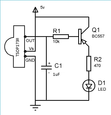
An IR remote circuit typically modulates a carrier frequency, often around 38 kHz, to encode commands using protocols such as NEC or RC5. The transmitter side includes a microcontroller or dedicated encoder IC that drives an infrared LED through a transistor or MOSFET. On the receiver end, a photodiode or integrated IR receiver module demodulates the signal and passes decoded data to a control unit. Single-sided CEM-1 PCB remote control design places all components on one surface, which simplifies layout but requires careful trace routing to avoid crosstalk between the oscillator and output stages. Power decoupling capacitors sit close to the microcontroller to maintain stable operation during transmission bursts. Proper ground plane usage on the single copper layer helps reduce noise in the IR signal path.
Designing a CEM-1 PCB for DIY Remote Control Projects
Layout begins with placing the microcontroller or encoder IC near the center of the board to minimize trace lengths to the IR LED and button matrix. Button inputs connect through pull-up resistors and connect to input pins with short traces to limit susceptibility to electromagnetic interference. The IR LED requires sufficient copper area for heat dissipation even at low duty cycles typical in remote use. Trace widths follow standard guidelines for current-carrying capacity, usually 0.3 mm or wider for signal lines and thicker for power paths. Component footprints adhere to manufacturer recommendations while respecting the single-sided constraint that prohibits through-hole vias for layer transitions. Hobbyists often prototype the IR remote circuit on a breadboard before committing to a CEM-1 PCB layout to verify timing and range.
Practical Assembly and Testing for Home Automation Projects
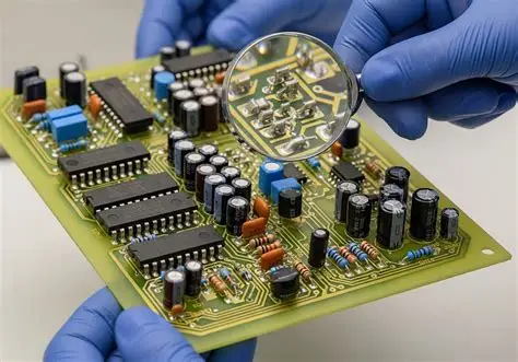
Assembly starts with applying solder paste or using a soldering iron to mount surface-mount components on the CEM-1 board. Through-hole parts such as the IR LED and crystal oscillator require careful alignment to avoid stressing the paper-based substrate. After soldering, visual inspection checks for bridges or insufficient wetting according to established acceptability guidelines. Functional testing involves powering the circuit and verifying that each button produces the expected modulated IR output using an oscilloscope or a simple receiver module connected to a microcontroller. Range testing in a typical room environment confirms reliable operation up to several meters. Troubleshooting common issues includes checking battery voltage under load and ensuring the carrier frequency remains stable across temperature variations encountered in household use.
Best Practices for Reliable CEM-1 PCB Remote Control Performance
Keep high-current paths short and wide to minimize voltage drop during LED activation. Position the IR LED at the edge of the board with a clear line of sight through the enclosure opening. Use decoupling capacitors rated for the operating voltage and place them as close as possible to power pins. For extended battery life in home automation projects, implement sleep modes in the microcontroller firmware to reduce quiescent current between button presses. Enclosure design should protect the board from dust and minor impacts while allowing easy battery replacement. These steps help maintain consistent performance over the life of the DIY remote control.
Conclusion
CEM-1 PCB remote control design offers hobbyists a straightforward path to create functional IR transmitters for home automation. The single-sided format reduces complexity and cost while supporting the modest requirements of typical remote circuits. Attention to layout, assembly quality, and testing ensures reliable operation in everyday environments. Following established industry practices helps produce durable boards that integrate smoothly into larger automation setups. This approach empowers electronic enthusiasts to build customized solutions without unnecessary expense or complexity.
FAQs
Q1: What considerations apply to CEM-1 PCB remote control design for hobbyists?
A1: CEM-1 PCB remote control design focuses on single-sided layouts that accommodate microcontrollers, IR LEDs, and button matrices with minimal trace routing. Hobbyists benefit from the material's low cost and adequate performance for low-power IR transmission. Proper component placement and decoupling practices help achieve stable operation. Testing the completed circuit verifies range and command accuracy before enclosure integration.
Q2: How does a single-sided PCB remote differ from multilayer alternatives in IR applications?
A2: A single-sided PCB remote uses one copper layer, which simplifies fabrication and reduces expense compared with multilayer boards. IR remote circuits rarely require high-speed signals or dense interconnects, making the single-sided approach sufficient. Trace routing must avoid long parallel runs that could introduce noise. This format supports straightforward DIY assembly while meeting the functional needs of most home automation projects.
Q3: What steps ensure reliable performance in a DIY remote control project using CEM-1?
A3: Reliable performance begins with accurate schematic capture followed by careful PCB layout that positions the IR LED for unobstructed transmission. Assembly follows standard soldering practices, and functional testing confirms modulation frequency and command decoding. Battery voltage monitoring and firmware sleep modes extend operational life. Enclosure design protects the board while preserving IR path clarity.
Q4: Why choose CEM-1 for an IR remote circuit in home automation?
A4: CEM-1 provides a cost-effective single-sided substrate suitable for the modest complexity of IR remote circuits. The material supports adequate thermal dissipation for LED operation and maintains mechanical integrity in handheld devices. Hobbyists can produce functional prototypes quickly without multilayer processing. This choice aligns with practical requirements for DIY home automation projects.
References
IPC-A-600K — Acceptability of Printed Boards. IPC, 2020
IPC-6012E — Qualification and Performance Specification for Rigid Printed Boards. IPC, 2017
JEDEC J-STD-020E — Moisture/Reflow Sensitivity Classification. JEDEC, 2014





