ALLPCB


Introduction
Building simple LED circuits is one of the most rewarding entry points into electronics for hobbyists. These circuits often consist of a power source, a resistor, an LED, and sometimes a switch, all connected on a basic PCB or breadboard. However, when the LED fails to light up or flickers erratically, frustration sets in quickly. Troubleshooting basic LED circuits requires a systematic approach to identify issues like poor connections or faulty parts. This guide provides practical steps tailored for electronic hobbyists, focusing on common pitfalls and reliable fixes. By the end, you'll confidently diagnose and repair your projects.
Why LED Circuit Troubleshooting Matters for Hobbyists
LED circuits form the foundation of many hobby projects, from decorative lights to simple indicators. Understanding how to fix issues builds essential skills in electronics diagnostics. Without proper troubleshooting, hobbyists waste time and components on repeated failures. It also prevents costly mistakes in larger builds, like custom PCBs. Mastering these techniques enhances project reliability and sparks creativity. Ultimately, effective troubleshooting turns setbacks into learning opportunities.
Understanding LED Circuit Basics and Common Failure Causes
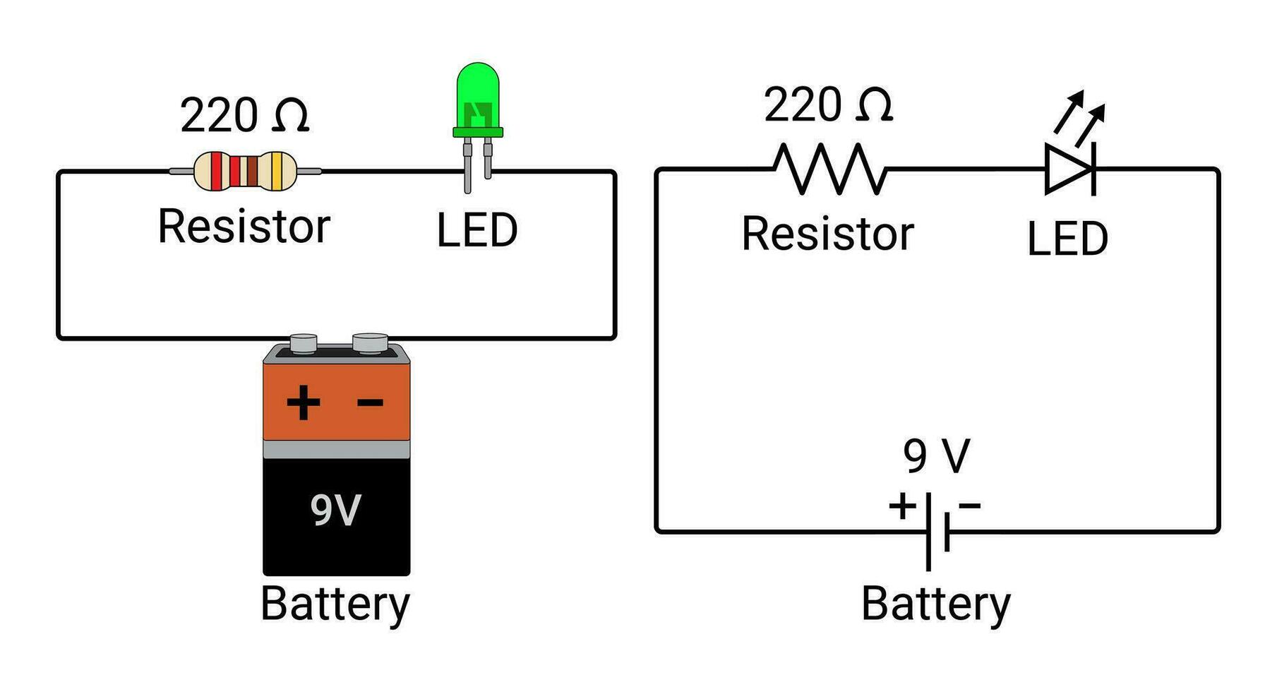
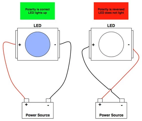
LEDs operate by allowing current to flow in one direction, emitting light when forward-biased. A typical circuit includes a current-limiting resistor to prevent excess current from damaging the LED. Power sources must match the LED's voltage requirements, often supplied by batteries or low-voltage adapters. PCBs in these circuits provide the conductive paths, but manufacturing defects can cause intermittent connections. Polarity errors are frequent, as LEDs only conduct when the anode connects to positive and cathode to negative.
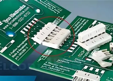
Common causes of failure include incorrect wiring, where reversed polarity stops current flow entirely. Overcurrent without a resistor leads to immediate burnout, heating the LED junction rapidly. Faulty solder joints on PCBs create high-resistance points, causing dimming or no light. Environmental factors like corrosion from humidity degrade contacts over time. Mechanical stress from mishandling can crack traces on fragile hobbyist PCBs.
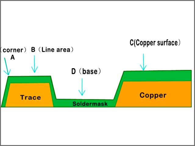
Adhering to standards like IPC-A-600K for printed board acceptability ensures PCB traces meet minimum width and spacing for reliable current flow. Poorly fabricated boards often show delamination or voids under inspection.
Identifying Faulty LED Components
Start with visual inspection to spot obvious issues in your LED circuit. Look for burnt marks on the LED dome, which indicate overcurrent exposure. Check resistor color bands for correct value; mismatches cause improper current limiting. On PCBs, examine solder joints for cold solder—dull, cracked appearances signal poor adhesion. Bent leads or loose components suggest mechanical failure during assembly.
To identify faulty LED components, gently test each LED individually. Insert it into a known good circuit or use a power source with series resistor. No light in both polarities confirms a dead LED. Resistors can be checked by measuring resistance; infinite or zero values mean open or shorted. Diodes in the circuit, if present, should block reverse current.
PCBs themselves may harbor faults like open traces, visible as breaks under magnification. Use continuity mode on a multimeter to probe pads. Standards such as J-STD-001G guide acceptable soldering practices, emphasizing fillet shapes and wetting for durable joints.
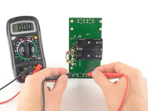
Testing LED PCBs with a Multimeter: Step-by-Step
Testing LED PCBs with a multimeter is a cornerstone of troubleshooting basic LED circuits. Power off the circuit first to avoid shocks or damage. Set the multimeter to continuity or diode mode for initial checks. Probe across the power supply terminals to confirm voltage matches LED needs, typically a few volts.
Next, test the resistor by measuring its value in ohms mode, out of circuit if possible. Verify polarity by checking forward voltage drop across the LED; it should read around 1.5 to 3 volts in diode mode, zero in reverse. On the PCB, use continuity beeps to trace paths from battery to LED. No beep indicates a broken trace or poor solder.
For powered tests, measure current through the circuit with the multimeter in series. Excessive readings point to resistor failure. Inspect ground connections last, as floating grounds cause erratic behavior.
Fixing Common LED Wiring Mistakes
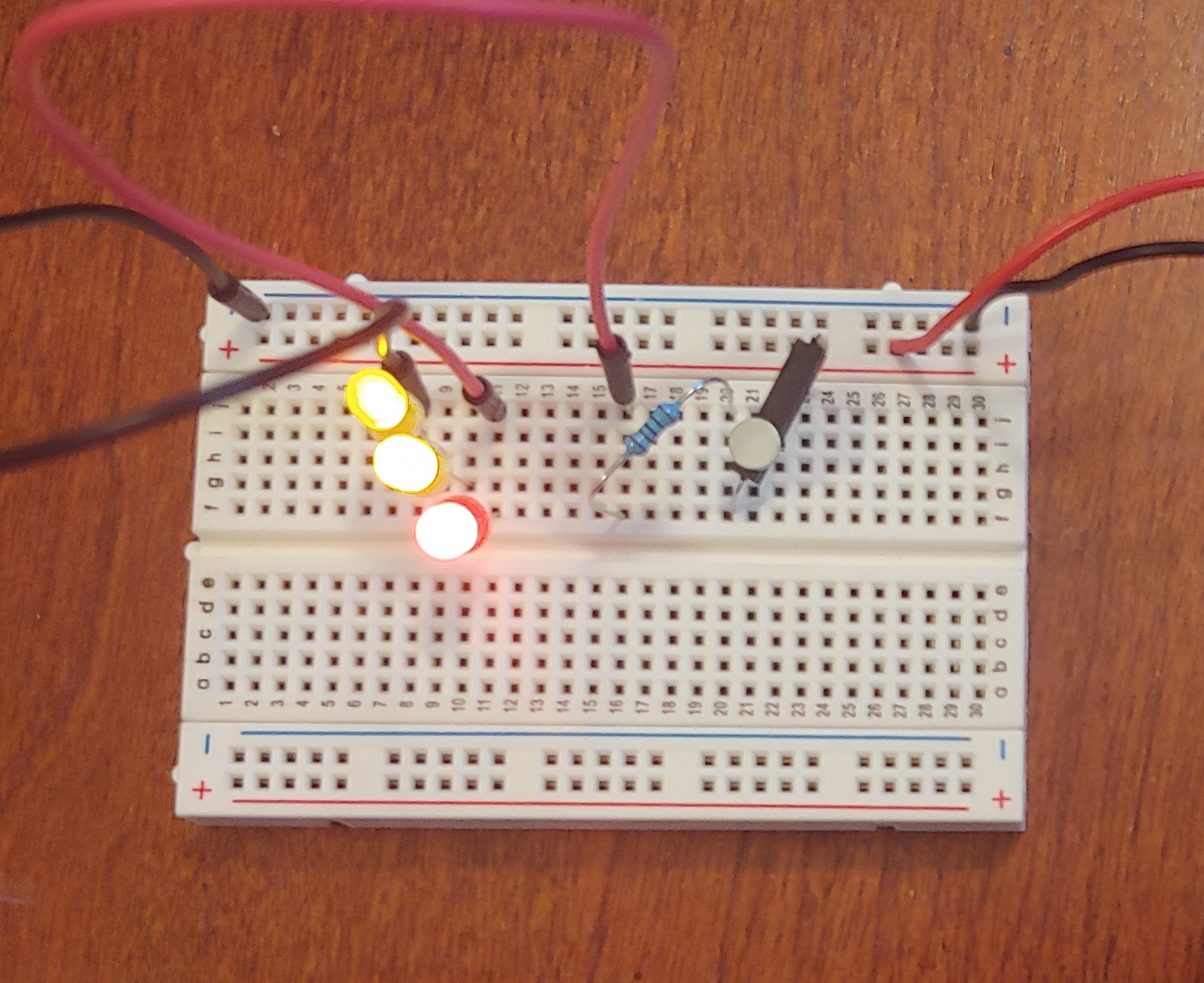
Fixing common LED wiring mistakes starts with breadboard verification before PCB commitment. Swap component positions to rule out polarity reversal. Breadboards often have loose contacts; reseat wires firmly. On soldered PCBs, reflow joints with a soldering iron at controlled temperature to avoid further damage.
Replace any suspect resistor with one of calculated value based on Ohm's law. Short traces show as zero resistance; scrape and bridge with wire if needed. Clean corrosion with isopropyl alcohol and a brush for restored conductivity.
Prevent recurrence by sketching schematics first. Label polarities clearly on prototypes.
Preventing LED Burnout in Hobby Projects
Preventing LED burnout extends circuit life and saves resources. Always include a series resistor sized for your supply voltage and LED current rating. Use datasheets for guidance, though hobby LEDs tolerate 10-20mA typically. Fuse the power line to cut off overcurrent automatically.
On PCBs, route traces wide enough per IPC-2221 design guidelines to handle current without heating. Avoid thin foils that increase resistance. Enclose sensitive circuits in cases to block dust and moisture.
Operate at reduced duty cycles for blinking LEDs, using timers if advanced. Monitor temperature during initial tests; warm components signal issues.
Real-World Troubleshooting Case Study
Consider a hobbyist building a panel indicator LED circuit on a perfboard PCB. The LED lights dimly then fades. Visual check reveals a cracked solder joint at the resistor leg. Multimeter confirms high resistance there, over 10k ohms instead of 330.
Resoldering fixes it temporarily, but flicker persists. Continuity test uncovers a hairline trace crack from board flexing. Bridging with solder wire restores full brightness. Final current draw measures safely at 15mA.
This case highlights sequential testing: visuals first, then electrical verification. It underscores PCB handling care to avoid mechanical faults.
Conclusion
Troubleshooting basic LED circuits empowers hobbyists to tackle projects confidently. From identifying faulty LED components to testing LED PCBs with a multimeter, systematic steps reveal root causes efficiently. Fixing common LED wiring mistakes and preventing LED burnout ensures reliable results. Reference standards like IPC-A-600K and J-STD-001G for professional-grade assemblies. Apply these techniques to iterate faster and innovate freely. Your next circuit will shine brighter.
FAQs
Q1: How do I start troubleshooting basic LED circuits that won't light up?
A1: Begin with power supply verification using a multimeter for correct voltage. Check LED polarity by swapping leads. Inspect wiring for loose connections or breaks. Test continuity across the PCB paths. This methodical approach, often resolving 80% of issues quickly, aligns with practical electronics diagnostics for hobbyists.
Q2: What are the most frequent mistakes when fixing common LED wiring mistakes?
A2: Overlooking polarity reversal tops the list, halting current flow. Forgetting the current-limiting resistor causes burnout. Poor solder joints on PCBs create resistance hotspots. Always verify schematics before soldering. Cleaning tools and using flux improves joint quality per assembly best practices.
Q3: How can I identify faulty LED components without spares?
A3: Use diode mode on a multimeter; forward bias shows voltage drop, reverse shows open. Visual scorch marks confirm damage. Test in a minimal battery-resistor setup. No glow in correct polarity means faulty. Isolate from PCB for accurate reads.
Q4: What steps prevent LED burnout in repeated hobby tests?
A4: Calculate resistor value precisely for your voltage and current. Add inline fuses for protection. Limit test durations to avoid heat buildup. Use PCB traces compliant with current capacity standards. Monitor with ammeter during operation. These habits extend LED life significantly.
References
IPC-A-600K — Acceptability of Printed Boards. IPC, 2020
J-STD-001G — Requirements for Soldered Electrical and Electronic Assemblies. IPC, 2011
IPC-6012E — Qualification and Performance Specification for Rigid Printed Boards. IPC, 2017