ALLPCB


Introduction
Magnetic resonance imaging (MRI) systems can produce high-resolution cross-sectional images of the human body, providing valuable diagnostic information. The RF probe is a critical component of an MRI system. The probe transmits a uniform RF magnetic field and receives the MR signals reflected from the body to reconstruct high-quality images. This article describes an electromagnetic analysis of an MRI probe.
Many MRI RF probes have been developed to improve filling factor and therefore signal-to-noise ratio. Noncylindrical coils have attracted attention for applications such as wrist or abdominal imaging. Elliptical coils are suitable for these clinical applications and for nonmedical uses such as analyzing packaged food. These coils are more complex to analyze theoretically and more difficult to realize practically, typically requiring birdcage-style analysis.
Elliptical Slot Oscillator Concept
Reference 3 proposed a simple, efficient elliptical slot oscillator as an alternative to an elliptical birdcage coil. Finite-element numerical calculations, with partial consideration of shielding effects, showed that the elliptical slot oscillator achieves field uniformity comparable to a noncylindrical birdcage coil while offering manufacturing and operational simplicity. The authors performed a transient analysis for a two-dimensional electromagnetic study of the unloaded elliptical slot oscillator.
The analysis yields the oscillator electromagnetic parameters: the inductance matrix [L] and capacitance matrix [C], accounting for all geometric parameters, and provides the simulated RF port frequency response S11. To demonstrate the oscillator performance in practice, the resonator was used as an RF probe in an optimized MRI system operating at 300 MHz (proton imaging). The resonator exhibited a minimum reflection of -73.27 dB and an unloaded quality factor of 500.
Equivalent Circuit and Geometry
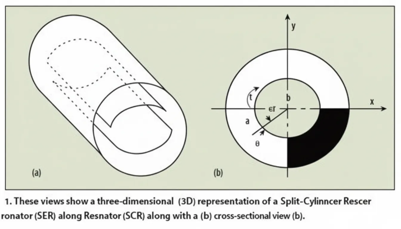
Figure 1 shows the equivalent circuit of the elliptical slot oscillator. The coil comprises two conductor plates of thickness t placed on opposite sides of a cylinder, carrying opposite currents. The plates can be mounted along the long axis (a) or the short axis (b) of the ellipse; finite-element analysis in Reference 3 indicates better field uniformity when the conductor plates are mounted on the short axis. The bottoms of the two conductor plates are connected by capacitors.
Figure 1b shows a cross section of the elliptical slot oscillator. The angle theta is referred to as the window angle. The optimum window angle depends on the ellipse aspect ratio a/b and the outer radius to long-axis ratio rb/a. The oscillator analyzed in Reference 3 used a/b = 1.8 and rb/a = 2.4, achieving optimal field uniformity at a window angle of 72 degrees. A shielded unloaded elliptical slot resonator electromagnetic behavior is characterized by primary parameters: inductance matrix [L] and capacitance matrix [C]; and a secondary parameter: the unloaded quality factor Qo. In [L], diagonal elements represent the self-inductance of conductor plates and off-diagonal elements represent mutual inductance. The [C] matrix represents capacitive effects between the two conductor plates. Together, [L] and [C] describe the resonator stored electromagnetic energy.
Simulation Method
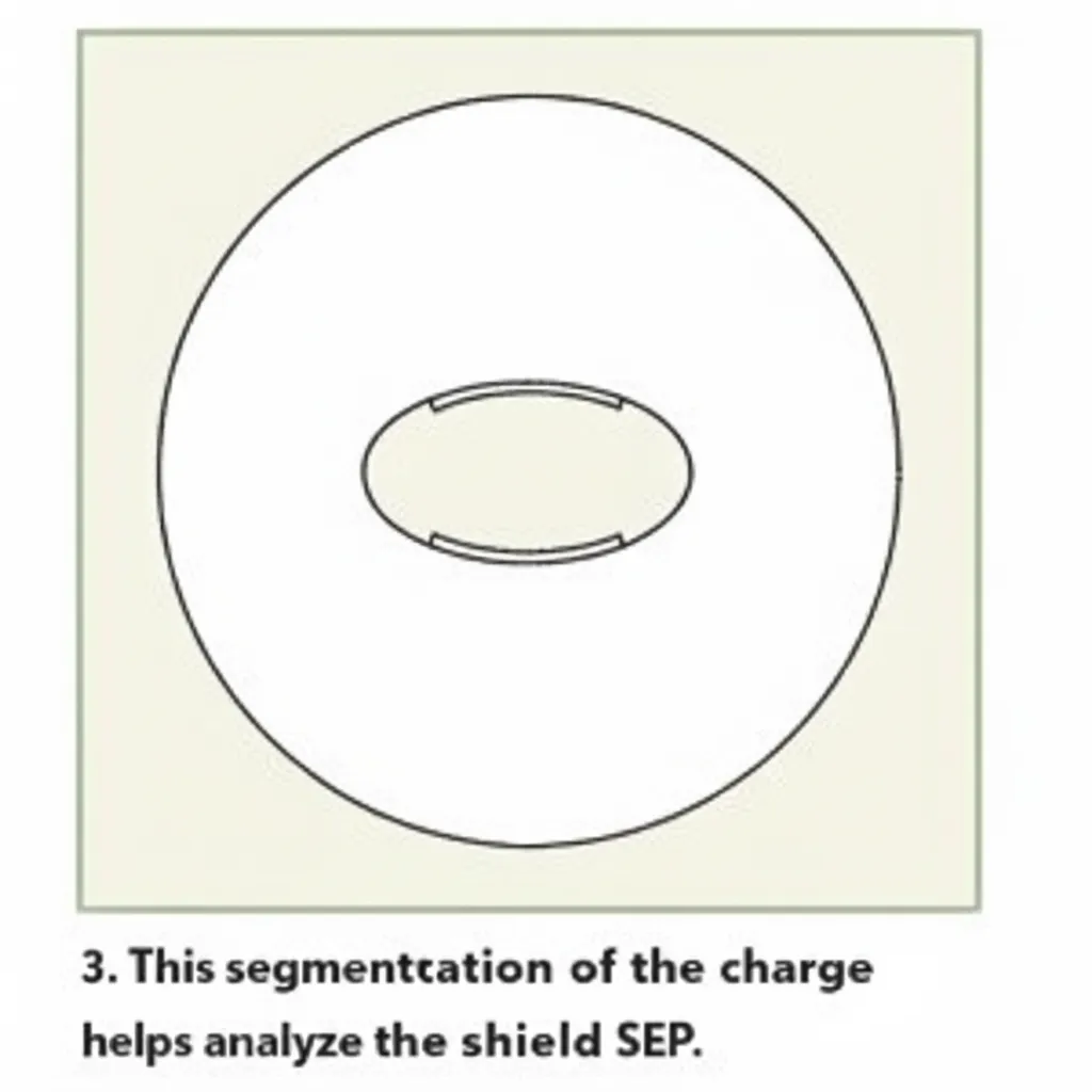
The Windows LINPAR program for multiconductor transmission line matrix parameters (Matrix Parameters for Multiconductor Transmission Lines) was used to compute the inductance matrix [L] and capacitance matrix [C]. LINPAR employs a transient method of moments (MoM) to compute quasi-static matrices for multiconductor transmission lines in piecewise-homogeneous media. The approach is based on static electromagnetic analysis. In the analysis, bound charges in dielectric regions are replaced by equivalent charges in vacuum and free charges represent conductors. Using the continuity of field components and boundary-condition-consistent charge distributions, a set of integral equations is obtained and solved by the MoM method. The total charge distribution is approximated by piecewise-constant segments and the Galerkin technique is applied.
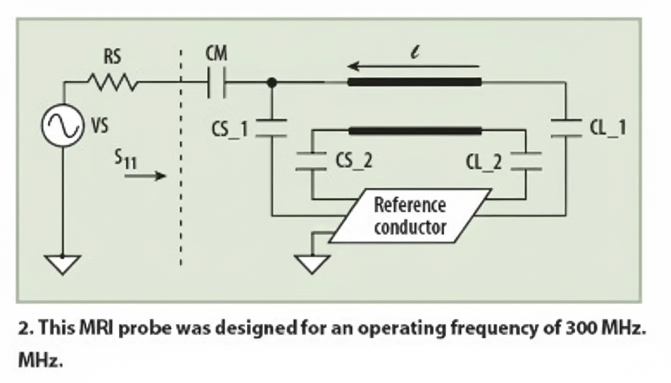
Once [L] and [C] are obtained, a corrected numerical model is used to estimate the resonator frequency spectrum and S11, as shown in Figure 2.
Probe Model and Quality Factor
The MR probe consists of a shielded elliptical slot resonator of length l, with matching capacitor CM and termination capacitors CSi and CLi (i = 1, 2).
By sweeping frequency and measuring the reflection coefficient S11, the unloaded quality factor Qo can be estimated. Here, fr is the resonant frequency; fu is the higher frequency at which the response is 3 dB down relative to the resonance; fl is the lower frequency at which the response is 3 dB down relative to the resonance.
Results from MoM Simulations
The MoM analysis enables simulation and assessment of whether the probe design can be realized. Figure 3 illustrates the LINPAR program segmentation of shielded resonator surface charge.
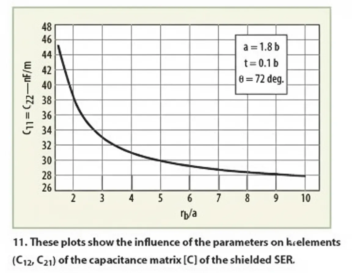
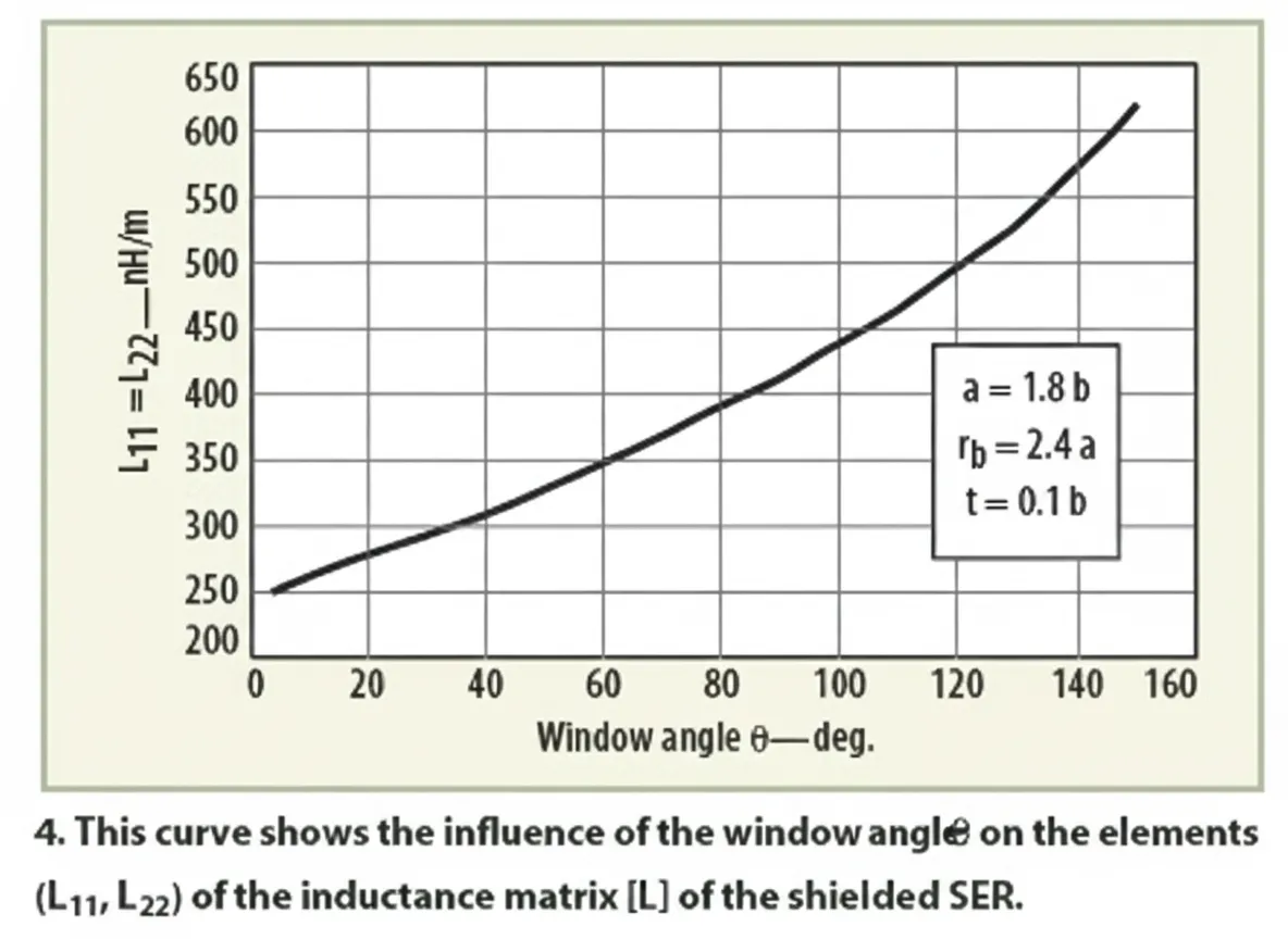
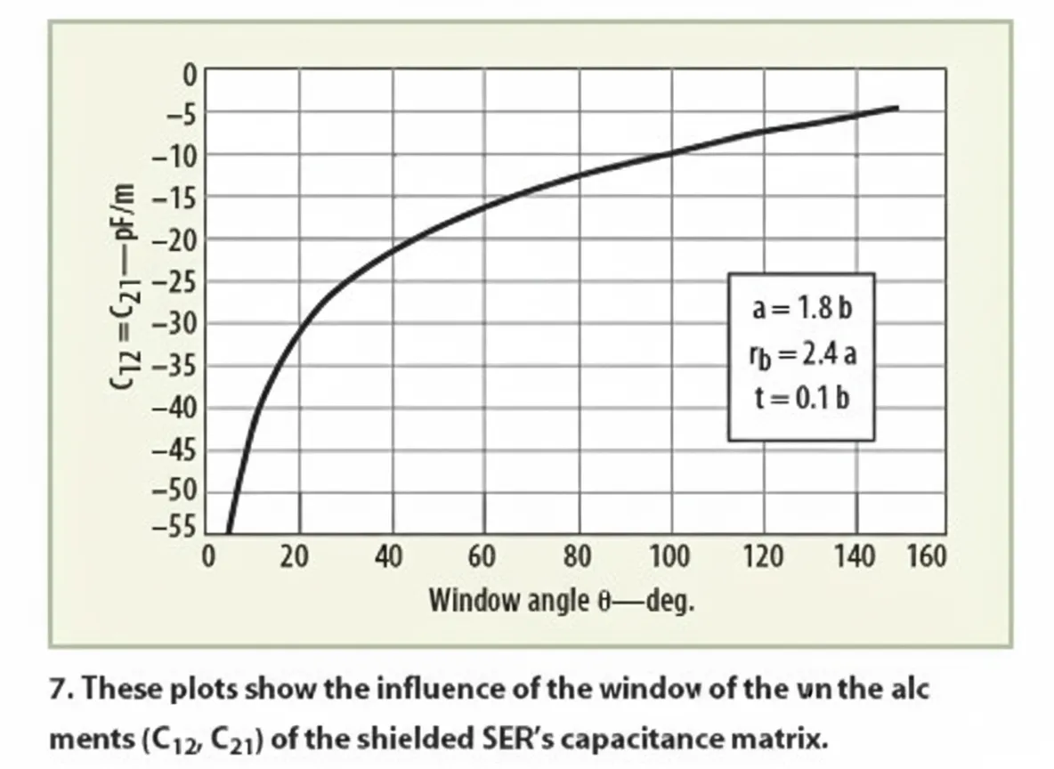
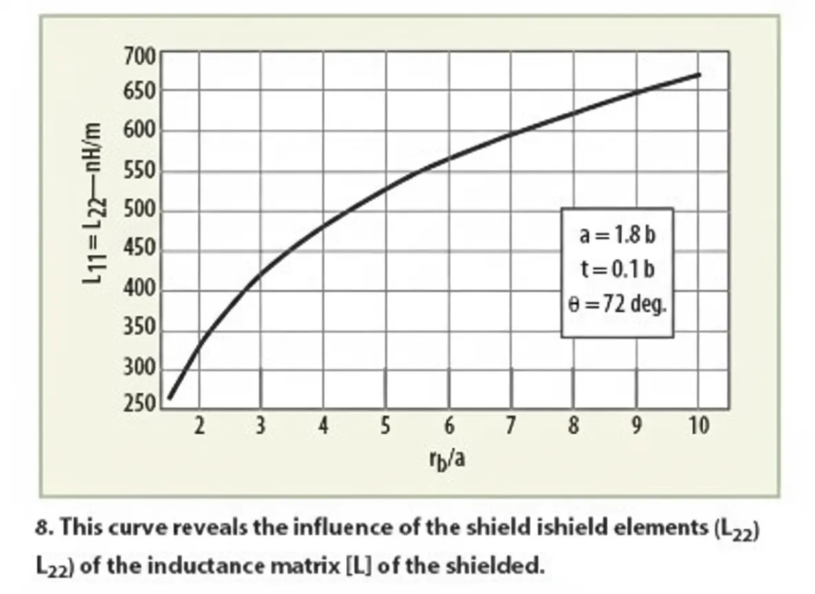
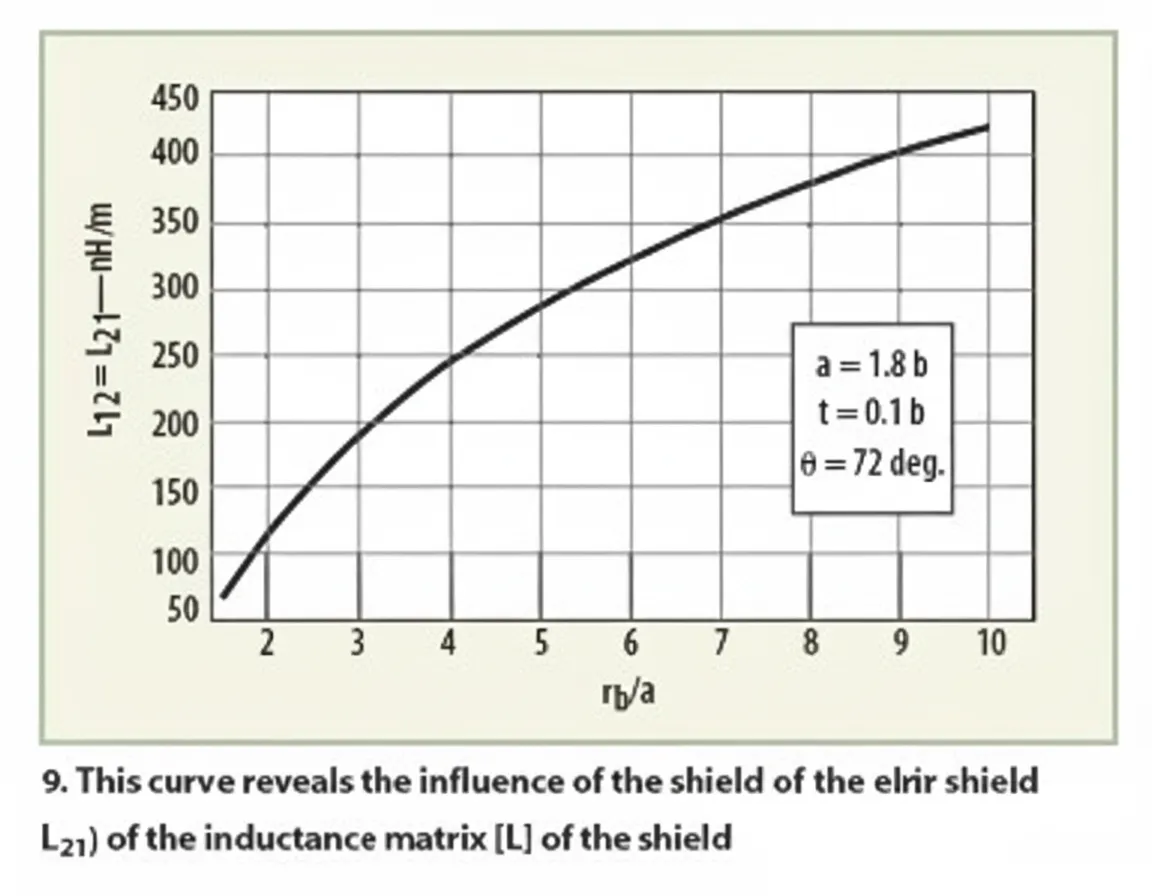
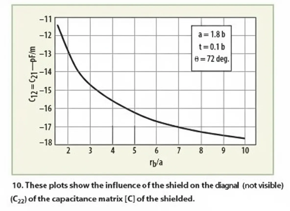
Figures 4 through 7 show the influence of the window angle theta on the electromagnetic parameters [L] and [C]. Figures 8 through 11 show the effect of the shield on these electromagnetic parameters.
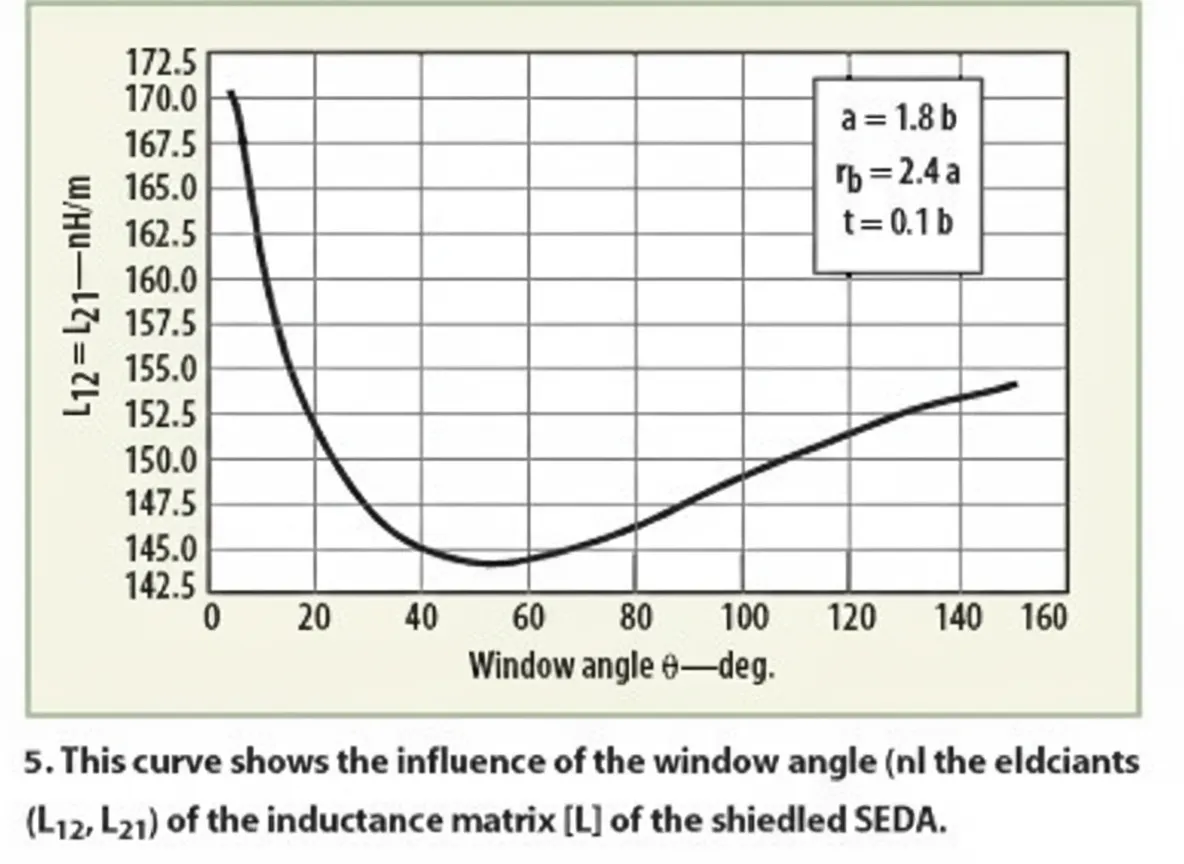
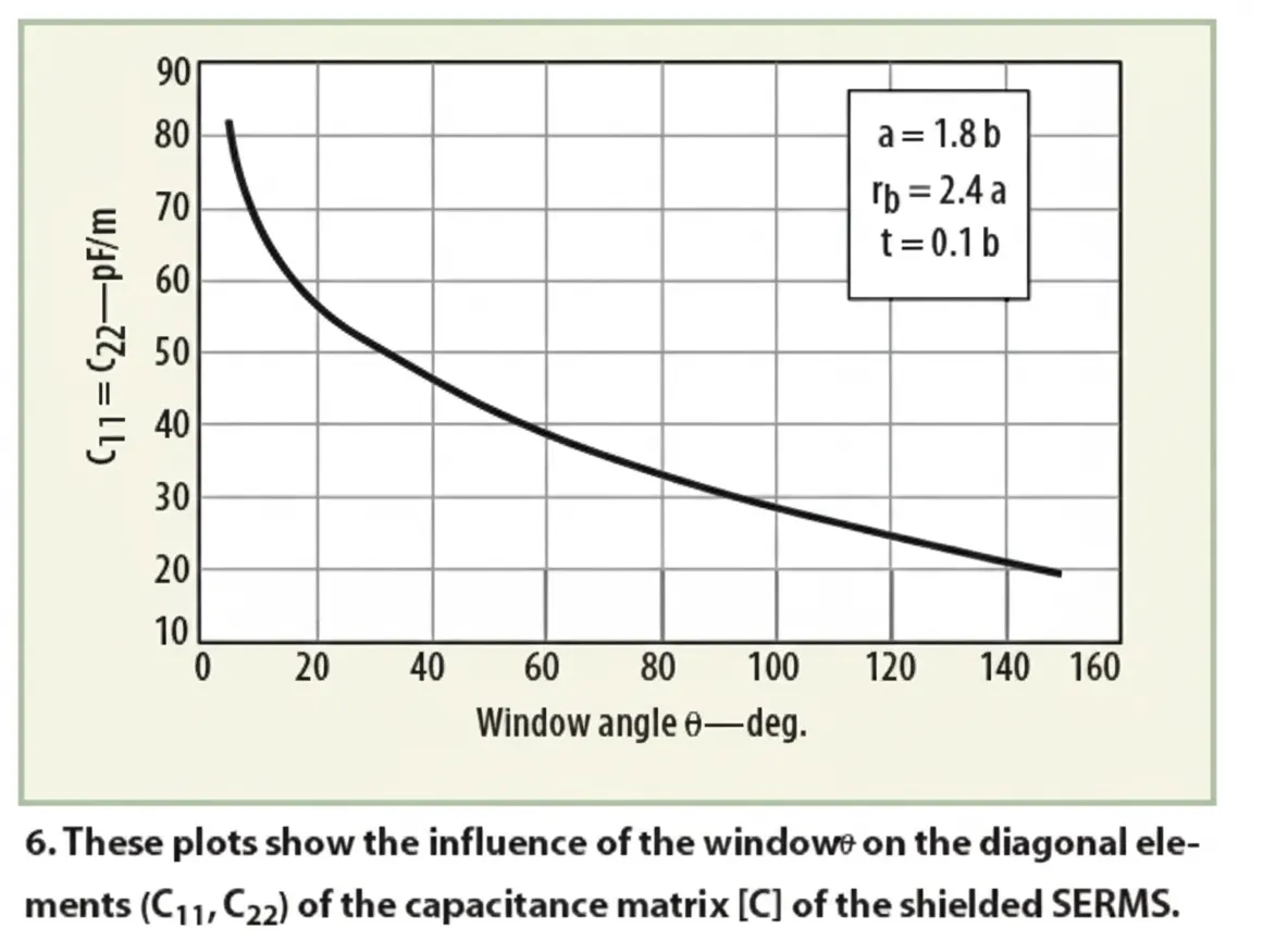
Using MoM, [L] and [C] matrices that include various geometric parameters were obtained. These results assist in designing MRI probes. For rb/a = 2.4 and theta = 72 degrees, the electromagnetic parameters of the resonator were derived.
The final MRI probe design parameters corresponding to Figure 2 are:
- Short axis b = 10 cm
- Aspect ratio a/b = 1.8
- Outer radius to long-axis ratio rb/a = 2.4
- Conductor thickness to short-axis ratio t/b = 0.1
- Window angle theta = 72 degrees
- Relative permittivity epsilon_r = 1
- Oscillator length l = 25 cm
- Matching capacitor CM = 20 pF
- Source and load termination capacitors CSi and CLi = 1 pF each
Figure 12 shows the simulated S11 at the RF probe port. The shielded resonator probe reaches its minimum reflection at the 300 MHz resonance.
Conclusion
This work presents a method for implementing an MRI probe using a shielded elliptical slot resonator. To reach the final design, the electromagnetic parameters of the shielded resonator must be determined. Using LINPAR, a two-dimensional MoM-based electromagnetic simulation tool, the quasi-static electromagnetic [L] and [C] matrices of the resonator were computed over the 150 to 520 MHz range. With the primary inductance matrix [L] and capacitance matrix [C], the RF probe port frequency response S11 and the unloaded quality factor Qo can be estimated.