ALLPCB


Introduction
In PCB manufacturing, drilling creates thousands of precise holes for vias and components, making drill bit performance central to production efficiency. PCB drill bit life directly influences throughput, as worn bits lead to defects like rough hole walls or breakage, increasing scrap rates. Factory operators focus on extending this life to achieve cost savings without compromising quality. By optimizing processes aligned with industry guidelines, manufacturers can reduce tool replacement frequency and downtime. This article explores practical strategies for electric engineers to maximize PCB drill bit life through material selection, maintenance, and parameter tuning.
Why PCB Drill Bit Life Matters in Manufacturing
Short drill bit life escalates operational costs, as bits represent a significant expense in high-volume runs. Each bit handles hits numbering in the tens of thousands before wear compromises hole accuracy, affecting plating and assembly yield. Poor bit performance also heightens risks of drill wander or breakage, violating acceptability criteria in standards like IPC-A-600. Engineers prioritizing PCB drill bit life ensure consistent hole geometries, supporting reliable signal integrity in multilayer boards. Ultimately, extending bit longevity translates to substantial cost savings and faster turnaround times in production lines.
Factory-driven insights reveal that proactive management of drill bit life minimizes unplanned stops for tool changes. This reliability becomes critical for rigid and flex-rigid boards where hole quality dictates overall board qualification under IPC-6012 specifications. Neglecting it leads to uneven copper deposition and potential field failures.
Technical Principles Behind Drill Bit Wear
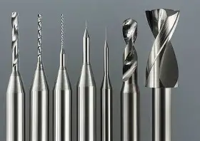
Drill bit wear in PCB manufacturing stems primarily from abrasive action of glass fibers in epoxy resins, accelerated by copper foil adhesion. High spindle speeds generate heat, promoting built-up edges on the bit flute that alter cutting geometry. Adhesive wear occurs when resin softens and sticks, while diffusion wear erodes the carbide substrate over repeated cycles. Understanding these mechanisms guides parameter adjustments to balance chip evacuation and tool integrity.
Helix angle and web thickness, as outlined in IPC-DR-572 drilling guidelines, influence heat dissipation and rigidity. Steeper helices aid chip removal but risk breakage in deeper holes, while shallower ones enhance stability at the expense of evacuation efficiency. Relief angles prevent rubbing along the hole wall, directly impacting bit life by reducing friction.
Material hardness of the board laminate exacerbates wear; denser glass reinforcement demands tougher bits. Vibration from stack drilling amplifies fatigue, leading to chipping at the margins.
Factors Affecting PCB Drill Bit Life
Board material properties dominate wear rates, with thicker copper layers causing faster flute dulling due to increased torque. High Tg resins resist heat better but their fillers abrade bits more aggressively than standard FR-4 equivalents. Drill bit material selection favors carbide over high-speed steel for its superior hardness and thermal resistance in PCB applications.
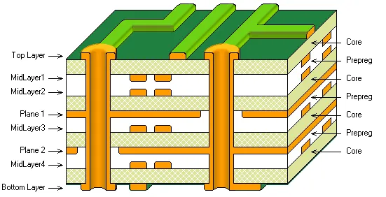
Optimal drilling parameters interplay with these factors; excessive feed rates overload the bit, while insufficient speeds fail to shear chips cleanly. Aspect ratios exceeding 10:1 strain bits through prolonged engagement, per general fabrication limits. Environmental controls like coolant flow mitigate thermal effects, though over-reliance risks resin swelling.
Stack height and entry-exit materials further modulate life; thin stacks reduce deflection but demand precise alignment to avoid burring.
Best Practices for Material Selection
Selecting carbide drill bits with appropriate coatings enhances durability against PCB-specific abrasives. Micrograin carbide offers finer grain structure for smaller diameters, resisting chipping in fine-pitch vias. Engineers should match bit geometry to board thickness and hole size, favoring 130-degree point angles for multilayer stacks.
Laminate selection indirectly aids bit life; lower glass transition materials drill easier but may require adjusted feeds. Consistency in supplier specs ensures predictable wear patterns across production lots.
Optimal Drilling Parameters for Extended Life
Tuning spindle speed and feed rate optimizes chipload, the material removed per flute revolution, to minimize heat buildup. Peck drilling with retract depths of 0.5 to 1 times diameter clears chips effectively, preventing packing that dulls margins. Start with conservative feeds for new bits, ramping as they break in to avoid early failure.
Hit counts per bit vary by setup, but monitoring via machine counters allows predictive replacement. Reducing panel warp through proper fixturing stabilizes entry, cutting lateral forces.
Factory protocols emphasize parameter matrices tailored to board types, ensuring compliance with hole tolerances in IPC-6012.
Drill Bit Maintenance and Sharpening Techniques
Routine drill bit maintenance involves visual and dimensional inspections post-shift to detect margin wear or flute clogging. Cleaning with compressed air or ultrasonic baths removes resin buildup, restoring cutting efficiency. Storage in dry, organized racks prevents oxidation and damage.
Drill bit sharpening restores geometry but requires precision grinders to maintain helix and relief angles per IPC-DR-572. Limit resharpenings to 5-10 cycles depending on diameter, as excessive grinding weakens the core. Dimensional checks post-sharpening verify tolerances before reuse.
Integrating automated sharpeners into workflows standardizes results, boosting overall PCB drill bit life.
Inspection and Monitoring Strategies
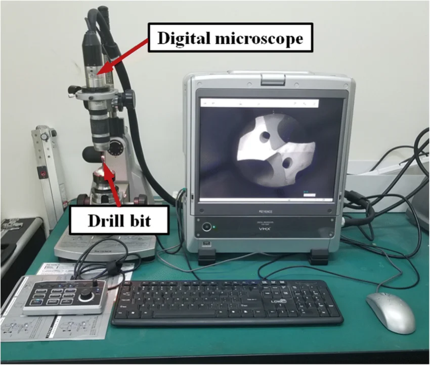
Inline microscopy or laser profilometers quantify wear by measuring flute radius increase. Tracking hits per bit via CNC software predicts end-of-life, enabling scheduled changes. Burr height gauges on sample holes correlate with bit condition, flagging issues early.
Trend analysis across lots identifies parameter drifts or material variations affecting life.
Troubleshooting Common Wear Issues
Excessive heat manifests as blackened chips and polished walls; counter with coolant optimization or speed reduction. Breakage often traces to misalignment or dull pilots; verify spindle runout below 0.01 mm. Nail heading from copper extrusion demands entry material upgrades.
Systematic root cause analysis, aligned with quality standards, resolves patterns for sustained improvements.
Conclusion
Maximizing PCB drill bit life demands integrated control of material selection, optimal drilling parameters, and rigorous maintenance. Factory engineers achieve cost savings by adhering to guidelines like IPC-DR-572 for geometries and IPC-6012 for hole performance. Consistent application yields reliable production, fewer defects, and economic gains. Implementing these tips elevates manufacturing precision and efficiency.
FAQs
Q1: What factors most impact PCB drill bit life?
A1: Board material abrasiveness, copper thickness, and drilling parameters like speed and feed primarily determine PCB drill bit life. Stack configuration and chip evacuation also play key roles. Proper monitoring prevents unexpected failures, supporting steady production. Aligning with IPC-DR-572 guidelines optimizes these elements for longevity.
Q2: How does drill bit sharpening extend tool life?
A2: Drill bit sharpening restores cutting edges, removing wear layers to recover geometry efficiency. Limit cycles to avoid core weakening, and inspect dimensions post-process. This maintenance practice, combined with cleaning, significantly prolongs usability in high-volume runs. It contributes to overall cost savings in PCB manufacturing.
Q3: Why is material selection crucial for optimal drilling parameters?
A3: Material selection for bits and boards ensures compatibility, reducing wear from mismatched hardness. Carbide suits glass-filled epoxies, while parameter tuning like peck depth matches laminate properties. This synergy maximizes hits per bit and hole quality. Engineers gain cost savings through fewer replacements.
Q4: What role does drill bit maintenance play in cost savings?
A4: Regular drill bit maintenance, including inspection and controlled sharpening, minimizes downtime and scrap. Clean bits drill cleaner holes, upholding standards like IPC-6012. Tracking usage patterns refines processes, extending life across production. These steps deliver direct cost savings without quality trade-offs.