ALLPCB


Overview
Shared power and data interfaces that are encoded can reduce the DC component of signals, simplifying system design when transmitting AC signal components. However, many digital-output sensor interfaces, such as SPI and I2C, are not encoded and have variable DC components, making them a poor natural fit for shared data-and-power designs.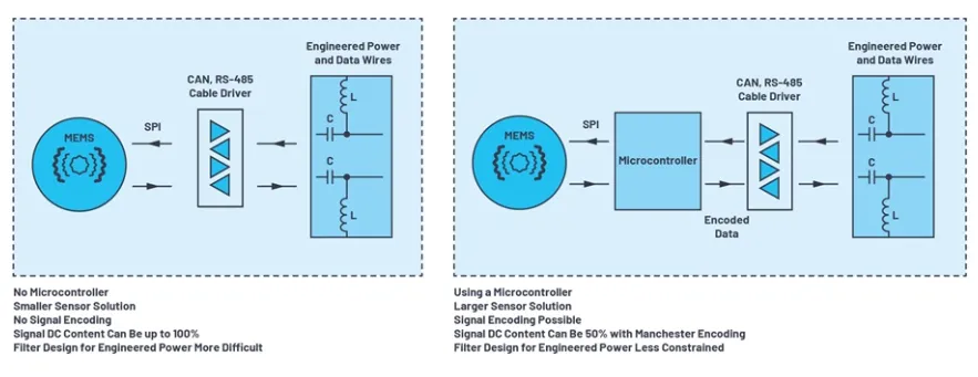
Several standards exist for sharing power and data on the same pair of conductors. Examples include IEEE 802.3bu for power over data lines (PoDL) and IEEE 802.3af for Power over Ethernet (PoE), which use dedicated power-interface controllers and provide controlled, safe power connections via detection, link checks, classification, and fault monitoring. These controlled power solutions typically cover power levels from a few watts to several tens of watts.
By contrast, the term "engineering power (EP)" refers to custom data-line power designs tailored for a specific application. EP is used in applications such as motor-control encoders and some sensor systems, where power and data are coupled onto the same conductor for the particular use case.
Engineering Power Background
Power and data are distributed over a pair of wires using inductive and capacitive networks. High-frequency data is coupled to the data line through series capacitors to protect communication transceivers from DC bus voltages. The master controller couples power onto the data line via an inductor, and the remote sensor node filters it with an inductor at the cable end.
The inductive-capacitive network produces high-pass filtering, so coupling solutions must be added when the data line needs no DC component. Some interfaces are not physically coded to remove DC components — SPI is an example. In such cases, designers must consider worst-case DC scenarios, e.g., when every bit in a data frame is a logic-high (100% DC component). The chosen inductors also have a specified self-resonant frequency (SRF); above the SRF the inductance falls and parasitic capacitance increases. Thus, an EP circuit will act as a band-pass filter, and analog modeling can greatly help designers understand these limitations.
SPI over Long Distances and Timing
When extending SPI over long distances, cable and component effects influence clock and data synchronization. The maximum achievable SPI clock is determined by system transmission delay, including cable propagation delay and device propagation delays at the master and slave nodes.
Simplified Circuit and Voltage-Drop Analysis
A simplified EP circuit can be used to analyze filtering, voltage drop, and voltage fall time. Due to the data-line power network inductance, the communication-bus voltage will sag. Voltage-drop analysis is important because bit errors can occur when the voltage drop exceeds a specified fraction of the peak voltage. Systems are often designed to meet specific voltage-drop and time-fall specifications. For example, 1000BASE-T assumes a 27% voltage drop within 500 ns.