ALLPCB


Introduction
Evoked potentials are characteristic electrical responses generated by the nervous system after external stimuli. They can be detected at relevant locations in the central and peripheral nervous systems and are time-locked to the stimulus. Evoked potentials provide quantitative and spatial information and are often more stable than routine electroencephalography, making them valuable for diagnosing and studying neurophysiological changes.
This project generates auditory and visual stimulus signals at specific frequencies to elicit evoked potentials. Clinicians can extract additional information from the evoked electroencephalogram to support diagnosis. The stimulator can produce audio and video stimuli. Audio stimuli include short clicks, pure tones, and user-recorded sounds; video stimuli include checkerboard reversals. Stimulus duration and frequency are configurable. The system is implemented primarily on an FPGA and related chips, using the ALTERA DE2 development board as the platform.
1 System Architecture
This design implements the stimulator functions using a popular FPGA and associated analog components. The block diagram is shown below.
Figure 1 Evoked potential system
Among existing products, some use many discrete components, increasing cost; some generate stimulus signals with analog components, limiting flexibility; and some store video images in flash memory, restricting storage capacity. With continuous FPGA improvements, it is possible to instantiate DSP soft cores and support C programming within the FPGA, enabling a single FPGA to implement all functions.
2 Hardware Design
This project produces auditory and visual stimuli at specific frequencies to elicit evoked potentials. Stimulus parameters such as frequency, duration, and mode are programmable, and it can play user-provided WAV audio files and display user-provided BMP images.
The system comprises the development platform, pure-tone (sine) and short-click audio output, audio input and output, and checkerboard-reversal video output.
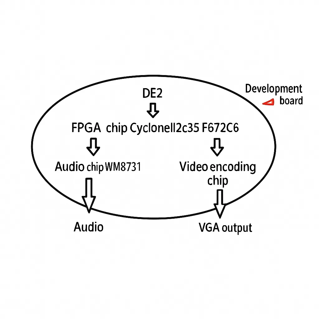
Figure 2 System composition
2.1 Development Platform
The development platform is the ALTERA DE2 board, which uses a Cyclone II 2C35 F672C6 FPGA. The design uses the onboard FPGA, a 24-bit CD-quality audio codec WM8731 (MIC input, LINEIN, LINEOUT), a video decoder supporting NTSC/PAL, and a VGA module with a high-speed DAC for video output.
This work primarily implements functions in the FPGA. FPGA and other programmable logic devices offer significant flexibility and are likely to remain important in electronic development. FPGAs act as semi-custom circuits in the application-specific integrated circuit domain, addressing limitations of custom circuits while providing expanded programmable resources.
2.2 Audio Input and Output Module
The design uses the WM8731 audio codec. WM8731 is a low-power, 24-bit stereo audio codec with features such as a high-performance headphone driver, controllable sampling rates, and selectable digital filters, making it suitable for portable players. The block diagram is shown below.
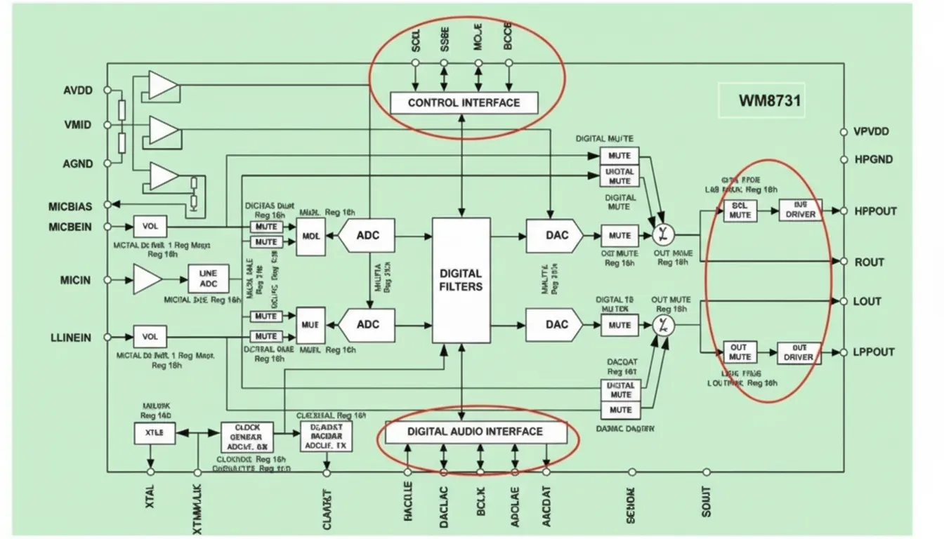
Figure 3 WM8731 block diagram
The WM8731 contains line input, microphone input, and headphone output with volume control. It integrates ADCs and selectable high-pass digital filters, and uses an oversampling DAC for line and headphone outputs. It includes a crystal oscillator and configurable digital audio interfaces, plus a 2- or 3-wire microcontroller control interface. A controller configures the WM8731 via the control interface, then reads and writes audio data through the digital audio interface. On the DE2 board, LINEOUT is derived from the headphone output after amplification and can directly drive headphones. LINEIN is AC-coupled through a capacitor, while MICIN can accept direct input.
The design uses the audio codec to generate pure tones and short clicks and to accept MIC audio input. After sampling, playback is via the LINEOUT interface.
Audio sample values span from -2^31 to 2^31-1. Pure tones are standard sine waves. A sine lookup table is created by sampling one period at 48 points and storing it in FPGA RAM. Table values are sent to the audio output at specific time intervals; changing the interval adjusts the tone frequency. Each pure tone plays for approximately 10 seconds, then a timer stops the sound. The pure tone waveform is shown below.
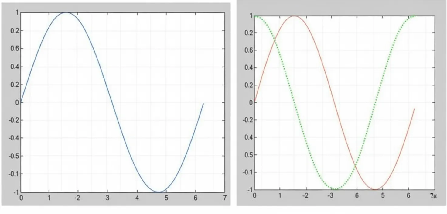
Figure 4 Pure tone waveform
Short clicks are square waves perceived as a "tick-tick" sound. Like pure tones, clicks are generated by timer-driven interrupts to the audio output. The click period is about 2 seconds, with 1 second on and 1 second off. Playback stops after about 10 seconds. The click waveform is shown below.
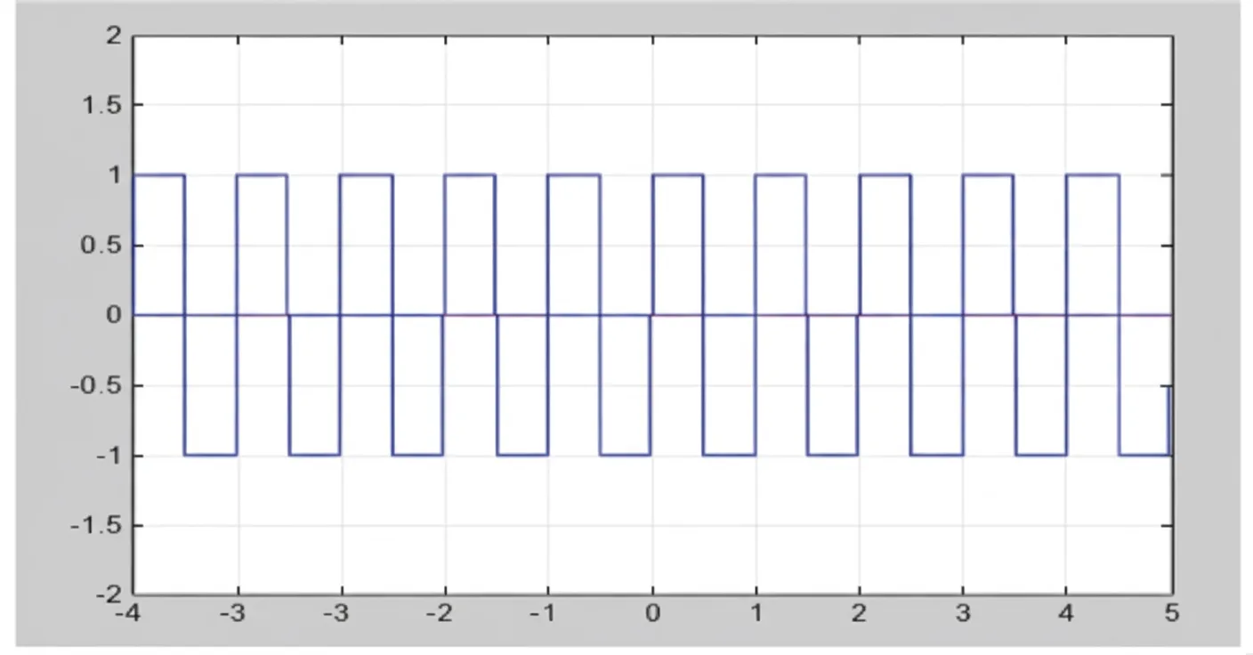
Figure 5 Click waveform
Audio input and output: a ~10-second sound clip can be recorded via the MIC input port. Audio sampling is at 48 kHz and playback occurs through the audio output port. Other behaviors match the pure tone and click functions.
2.3 Video Output Module
VGA is the standard interface for connecting to monitors. For standard VGA, signals include the three color channels R, G, B and horizontal and vertical sync signals HS and VS. This design only requires a luminance signal, so the G channel is used. HS and VS signals must be generated to match VGA timing. Horizontal and vertical sync determine the start and end times of each line and frame, ensuring image data scans left-to-right and top-to-bottom to form frames. The VGA display module block diagram is shown below.
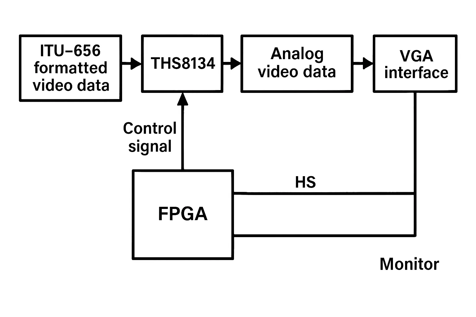
Figure 6 VGA display module block diagram
The video stimulus output is a checkerboard reversal. Test parameters: 4x4 tiles, alternating black and green. Reversal frequency is 1 Hz, stimulus duration is 10 seconds.