ALLPCB


Introduction
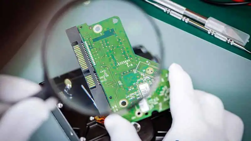
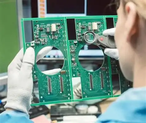
As an electronic hobbyist, you might start with simple circuits on breadboards, but once you move to custom printed circuit boards (PCBs) for faster projects like data logging or sensor arrays, signal integrity becomes crucial. Issues such as crosstalk, impedance mismatch, and signal reflections can turn a promising design into a frustrating one filled with erratic behavior or data errors. These problems arise when high-speed signals travel across your PCB traces, interfering with each other or bouncing back unexpectedly. Understanding them helps ensure clean signals, reliable performance, and fewer debugging hours. This guide breaks down each concept simply, explains why they matter for hobbyist builds, and shares practical fixes. By the end, you will know how to spot and solve these signal integrity challenges in your next project.
Signal integrity refers to maintaining the electrical quality of signals from source to destination. In PCBs, poor signal integrity leads to bit errors, timing issues, or complete system failure, especially at speeds above a few megahertz. Hobbyists often encounter these when upgrading from low-speed microcontrollers to interfaces like SPI, I2C at high rates, or even basic USB. Crosstalk couples noise between traces, impedance mismatch causes energy to reflect, and together they degrade your signals. Following basic design principles aligned with industry standards can prevent most issues without advanced tools.
What Is Crosstalk and Why Does It Matter?
Crosstalk occurs when a signal on one PCB trace induces unwanted noise on a nearby trace through electromagnetic coupling. There are two main types: capacitive crosstalk, which happens via electric fields between close conductors, and inductive crosstalk from magnetic fields linking changing currents. In hobbyist PCBs, this shows up as glitches or voltage spikes on quiet lines, corrupting digital signals or adding noise to analog ones. For example, a fast clock line might inject pulses into an adjacent data line, causing false triggers in your circuit.
Why does crosstalk matter for beginners? At low speeds, it might be negligible, but as hobby projects push higher frequencies, like in wireless modules or fast ADCs, it directly impacts signal integrity. Unchecked crosstalk can make your board unreliable, leading to intermittent failures hard to diagnose with basic scopes. Industry standards like IPC-2221 provide guidelines on trace spacing to minimize this coupling. Hobbyists benefit by spacing critical traces farther apart during layout.
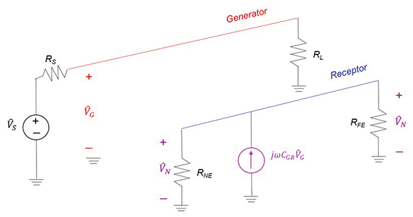
The strength of crosstalk depends on trace length, separation, and rise time of the aggressor signal. Longer parallel runs amplify the effect, as fields have more time to couple energy. Faster edges, common in modern logic, worsen it because higher frequencies carry more energy in harmonics. To quantify, near-end crosstalk voltage can be estimated simply, but for hobbyists, visual rules suffice: keep sensitive traces at least three times the trace width apart.
Understanding Impedance Mismatch
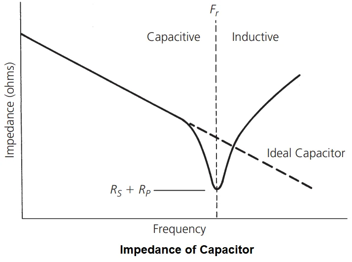
Impedance mismatch happens when the characteristic impedance of a PCB trace does not match the source driver's output impedance or the receiving load. Characteristic impedance, typically 50 or 100 ohms for hobby designs, depends on trace width, thickness, dielectric height, and material properties. A mismatch creates a discontinuity, like a sudden change in pipe width for the signal wave. This forces part of the signal to reflect back instead of transmitting fully.
For electronic hobbyists, impedance mismatch often sneaks in during routing changes or via placements, degrading signal integrity without obvious signs. It causes overshoot, undershoot, or ringing, visible on scopes as wiggles after edges. In multi-layer boards, ignoring stackup details leads to varying impedance along the trace. Standards such as IPC-2141A guide controlled impedance design by outlining calculations for microstrip and stripline geometries.
Mismatches are common in beginner layouts with bends, stubs, or unterminated lines. Signals above trace length times frequency over speed of light (roughly 15 cm/GHz rule) behave as transmission lines, demanding matches. Hobbyists can start with 50-ohm traces for single-ended signals, adjusting width via online calculators tied to FR4 properties.
Signal Reflections Explained
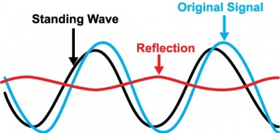
Signal reflections occur when a voltage wave encounters an impedance change, bouncing back toward the source like an echo in a pipe. The reflection coefficient determines amplitude: full open (infinite Z) reflects positive, short (0 Z) negative, matched (no reflection). In PCBs, vias, connectors, pads, or trace ends create these discontinuities. Reflections superimpose on the original signal, causing distortion that propagates further.
Beginners notice reflections as eye closure or jitter in high-speed hobby links, harming signal integrity. For instance, an unterminated 100-ohm differential pair reflects half the energy back. Propagation delay in traces (about 150 ps/inch in FR4) sets the round-trip time for ringing. IPC-2141A details how to model and test for these in high-speed designs.
Reflections worsen with multiple discontinuities, summing to unpredictable waveforms. Short traces under 1/10 wavelength often tolerate them, but hobby Ethernet or LVDS pushes limits. Series resistors at drivers or parallel terminations absorb energy, restoring clean edges.
How These Issues Interconnect in PCB Design
Crosstalk, impedance mismatch, and signal reflections often compound each other, amplifying signal integrity problems. A mismatched via not only reflects but also radiates, increasing crosstalk to neighbors. Reflections from one end can couple inductively into parallel aggressors, creating feedback loops. In dense hobby boards, tight spacing exacerbates all three.
Understanding interactions helps prioritize fixes. Impedance control reduces reflections, inherently cutting radiated energy for less crosstalk. Proper spacing per IPC-2221 guidelines tackles coupling while aiding uniform fields for stable Z0. Hobbyists see this in prototypes: fixing one reveals others.
Via stubs from unrouted inner layers cause severe mismatches and resonances. Clock harmonics excite crosstalk peaks. Holistic design views the PCB as a system.
Practical Solutions and Best Practices
Start with controlled impedance: calculate trace widths for your stackup using field solvers or formulas from IPC-2141A. For 1.6 mm FR4 two-layer, 50 ohms needs about 3 mm wide traces external. Specify tolerances like +/-10 percent in fab notes. Multi-layer? Reference planes tighten fields, lowering Z0 and shielding crosstalk.
Routing best practices curb issues. Route high-speed traces straight, minimize vias, length-match pairs. Space parallels 3-5x dielectric height; orthogonal for low coupling. Avoid 90-degree bends; use 45s or curves to preserve Z0. Ground planes under signals return currents close, slashing inductance and emissions.
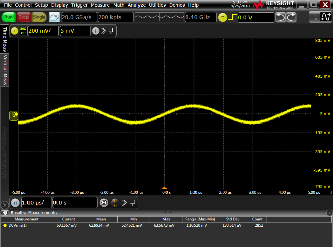
Termination schemes suit hobby needs. Source series resistors (22-33 ohms) match driver Z, simple for CMOS. End parallel 50/100 ohms for open lines. AC coupling capacitors block DC while passing high-freq. Test with scopes: clean 1 GHz edges mean success.
Layer stackup matters: signal-ground-signal reduces loop area, impedance. Fill unused areas with ground pours, stitched vias. Decoupling caps near ICs fight ground bounce aiding reflections.
Power integrity ties in: clean supplies prevent noise injection mimicking crosstalk. Wide pours, planes, bypasses.
Troubleshooting Common Signal Integrity Issues
Spot problems with affordable tools: hobby scopes (100 MHz plus) show ringing, overshoot. Logic analyzers catch glitches from crosstalk. Near clean signals? Shorten traces, add ground.
Persistent ringing? Measure Z0 with TDR if possible, or width-check. Crosstalk spikes? Increase spacing, shorten parallels, add guards.
Prototype iteratively: simulate free tools first, then build. Thermal imaging spots hot reflections indirectly.
Case: Hobbyist SPI bus at 20 MHz fails intermittently. Crosstalk from clock to data fixed by 5 mm spacing, 33R series. Reflections gone with matched lengths.
Conclusion
Mastering crosstalk, impedance mismatch, and signal reflections elevates your PCB designs from basic to robust. These signal integrity pillars ensure reliable high-speed hobby projects. Apply spacing rules, control Z0, terminate wisely, guided by standards like IPC-2141A and IPC-2221. Start simple, test often, iterate. Your next board will perform flawlessly.
FAQs
Q1: What causes crosstalk in PCB designs for hobbyists?
A1: Crosstalk arises from electromagnetic coupling between adjacent traces, mainly capacitive from electric fields and inductive from magnetic fields. Parallel runs over 1/4 wavelength worsen it, injecting noise into victims and harming signal integrity. Space traces at least 3x height, route orthogonally, use ground planes between. IPC-2221 offers spacing charts. Test with scope probes.
Q2: How do I fix impedance mismatch in my beginner PCB?
A2: Calculate trace width for target Z0 using stackup details, like 50 ohms needing wider copper on FR4. Avoid vias, bends disrupting it. Specify controlled impedance to fabricator. Mismatch causes reflections distorting edges. IPC-2141A guides calculations. Verify post-fab with network analyzer if available.
Q3: Why are signal reflections a big deal for signal integrity?
A3: Reflections from Z discontinuities superimpose, causing overshoot, ringing, eye closure in fast signals. Unterminated lines reflect fully, summing multiples. Keep traces short, match source/load. Reflections couple as crosstalk too. Proper termination absorbs waves cleanly.
Q4: Can hobbyists achieve good signal integrity without fancy tools?
A4: Yes, follow rules: controlled Z0, spacing, planes, short paths. Free calculators simulate. Scope prototypes for waveforms. Standards like IPC-2141A provide formulas. Iterate boards cheaply.
References
IPC-2141A - Design Guide for High-Speed Controlled Impedance Circuit Boards. IPC, 2004
IPC-2221B - Generic Standard on Printed Board Design. IPC, 2003
IPC-6012E - Qualification and Performance Specification for Rigid Printed Boards. IPC, 2017