 ALLPCB


Overview
It is common to see a resistor placed in series with a MOSFET gate. Why add this resistor, and more specifically, why is a value such as 100 Ω often used?
Why place a resistor at the MOSFET gate?
MOSFETs are voltage-controlled devices. Under normal conditions, conduction is controlled by the gate voltage exceeding the threshold; the gate does not require DC current. In that sense, no series resistor is strictly required at the gate.
However, the MOSFET gate has parasitic capacitances. To speed up switching and reduce switching losses, the effective resistance seen by the gate should be as small as possible to achieve fast transitions.
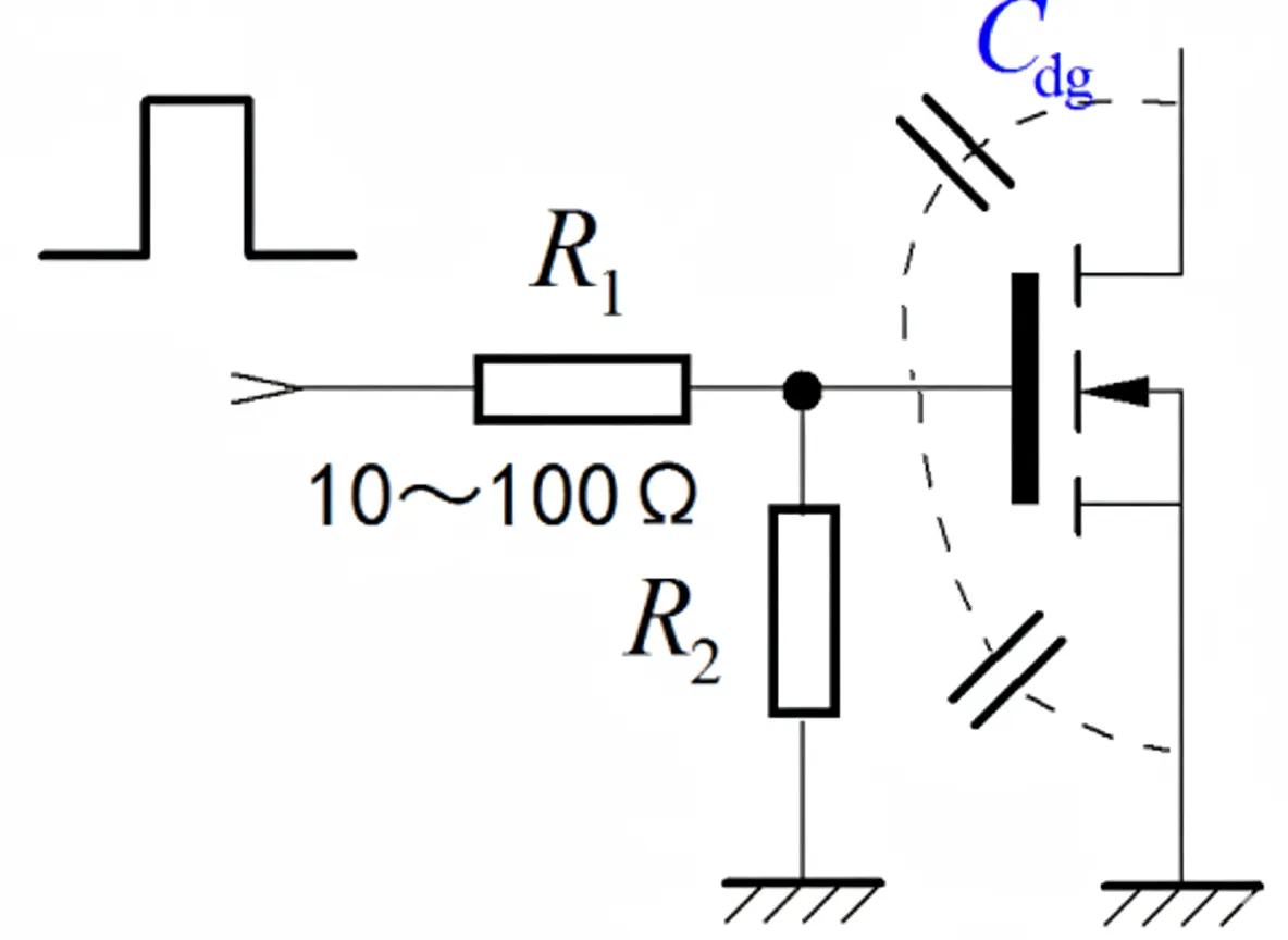
Despite that, many MOSFET circuits include a series resistor at the gate, as shown below.
Purpose of the gate resistor
In switching applications, a common explanation is that the gate resistor prevents oscillation during switching. Oscillation increases switching losses and, if severe, can lead to MOSFET failure.
For example, a simulation compared gate series resistor R3 at 1 Ω, 10 Ω, and 50 Ω:
- 1 Ω: the output Vds shows high-frequency ringing.
- 10 Ω: the Vds ringing is significantly attenuated.
- 50 Ω: the Vds rise becomes slower; the Miller capacitance effect between drain and gate causes a stepped waveform on the gate voltage, increasing MOSFET losses.
In short, a too-small resistor causes ringing; a too-large resistor slows the switching transition and increases switching losses.
How the gate resistor suppresses oscillation
Consider a MOSFET driver circuit with distributed inductances such as the inductor L shown below. Those inductances together with the MOSFET parasitic capacitances Cgd and Cgs form resonant circuits. They resonate with high-frequency components of the drive signal and cause output voltage fluctuations. A gate series resistor Rg increases damping in the drive loop, lowering the resonant circuit Q and causing the resonance to decay more rapidly.
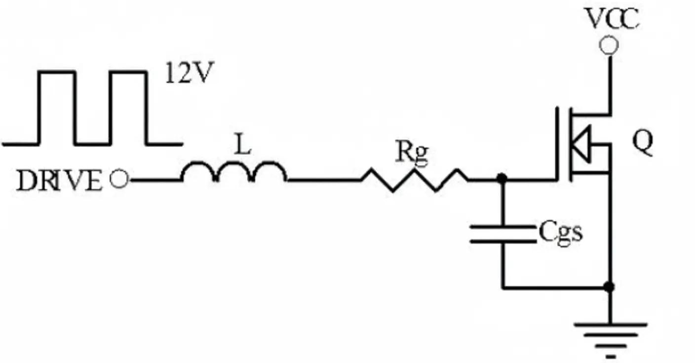
The appropriate Rg depends on the specific MOSFET and the circuit layout stray inductances. The effects illustrated below apply:
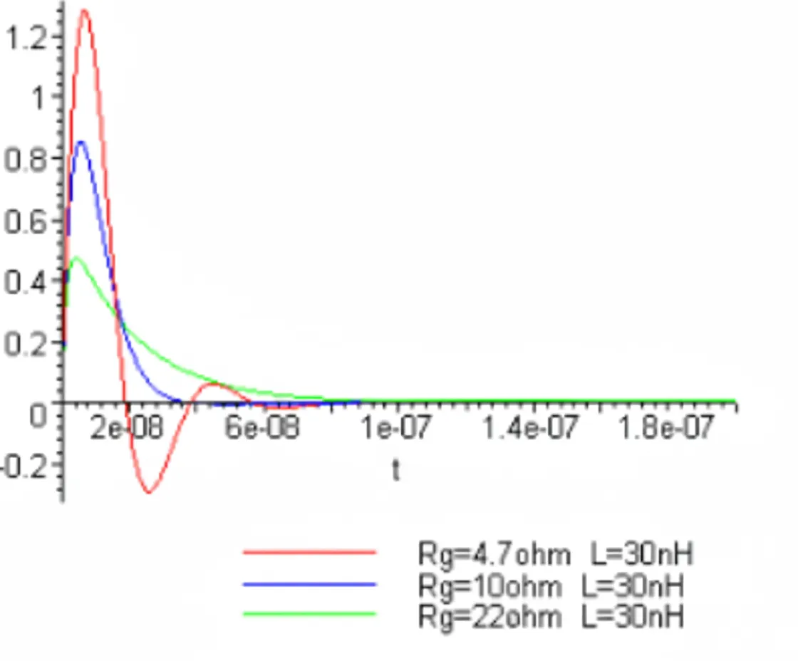
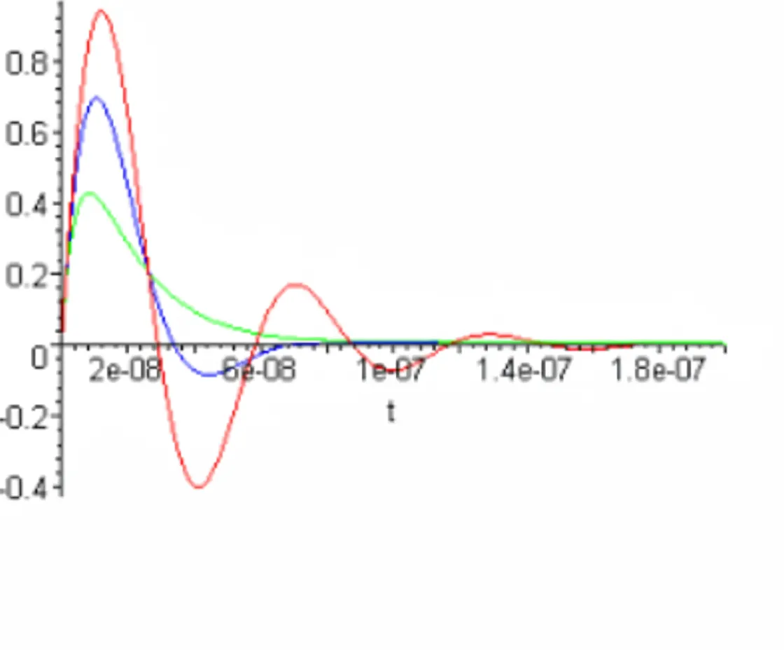
When Rg is small, the drive voltage overshoot and ringing are larger; the larger the inductance L, the more pronounced this becomes. Peak drive current is also higher, but driver ICs have finite current capability.
When Rg is large, the gate is charged more like a linear charge at the driver IC output current limit, so the gate voltage rise rate slows. Slower rise is disadvantageous when the MOSFET is conducting significant current, because it increases switching losses.
Choosing the resistor value
Both excessive and insufficient gate resistance negatively affect MOSFET switching performance. The appropriate value is chosen based on the MOSFET current and voltage ratings, switching frequency, and the circuit layout stray inductances. In practice, designers select Rg to balance damping of parasitic resonances and acceptable switching speed.


