ALLPCB


Introduction
When referring to TVS (transient voltage suppressors), most electronic engineers know they are used to protect ports against instantaneous voltage transients that could damage downstream circuits. Because of their important role, many manufacturers simply recommend a specific device for a circuit without providing theoretical calculation for selection. As a result, experienced engineers rely on experience and newcomers rely on references. When suppliers or test conditions change, designers may be unsure how to proceed. This article explains the TVS selection process so both experienced and new engineers can make informed choices.
1. TVS Operating Principle
TVS devices are semiconductor-based components formed by one or more PN junctions. They are also called avalanche diodes. TVS devices come in unidirectional and bidirectional types. Unidirectional TVS devices are typically used in DC power circuits; bidirectional types are used where voltage alternates. In a DC circuit, a unidirectional TVS is connected in reverse across the circuit. Under normal operation the TVS is off (high resistance) and does not affect the circuit. When an abnormal overvoltage reaches the TVS avalanche breakdown voltage, the device rapidly switches to a low-resistance state and shunts the transient current to ground, clamping the voltage to a lower level to protect downstream circuits. When the transient ends, the TVS returns to its high-resistance state.
2. Key TVS Parameters
To use TVS devices effectively, it is necessary to understand their key parameters.
(1) Vrwm – Reverse standoff voltage
Vrwm is the maximum continuous peak or DC voltage that can be applied to the TVS without causing degradation or damage. For AC voltages, Vrwm is expressed as the RMS value. At Vrwm the TVS is considered non-conductive. In other words, the circuit's maximum operating voltage must be lower than Vrwm; otherwise the TVS may conduct and affect normal circuit operation.
(2) IR – Leakage current
Leakage current, also called standby current, is the maximum current flowing through the TVS under specified temperature and maximum operating voltage conditions. IR is typically measured at Vrwm. For the same power and voltage ratings, when Vrwm ≤ 10 V a bidirectional TVS has about twice the leakage current of a unidirectional TVS. For some analog ports, leakage current can affect ADC sampling, so lower IR is preferable.
(3) VBR – Breakdown voltage
VBR is the voltage measured across the TVS under the specified pulse DC test current IT (commonly around 10 mA) or under a current approaching avalanche conditions. The applied current duration should not exceed 400 ms to avoid damaging the device. VBR MIN and VBR MAX define allowable variation, typically ±5%. A device measured with VBR between VBR MIN and VBR MAX is considered acceptable.
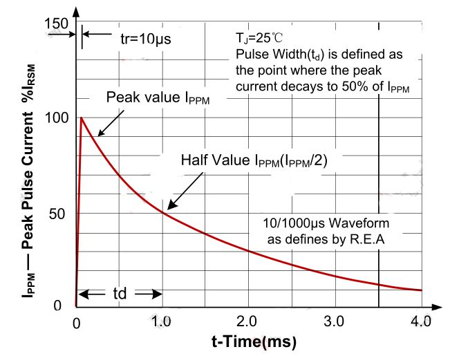
(4) IPP – Peak pulse current and VC – Clamping voltage
IPP is the peak of a specified pulse current waveform, commonly 10/1000 μs for TVS testing. VC is the peak voltage measured across the TVS when the specified peak pulse current IPP is applied. IPP and VC indicate the TVS capability to withstand surge currents and to clamp voltages. For surge protection characteristics, VC is the parameter to reference: at the same IPP, a lower VC indicates better clamping performance. IPP indicates the pulse current handling capability: larger IPP means stronger surge tolerance.
(5) Junction capacitance CI and leakage IR
Junction capacitance is a parasitic parameter relevant for high-speed I/O protection; excessive capacitance can degrade signal integrity. Leakage current leads to power loss and can affect ADC sampling in analog circuits.
3. TVS Selection Process
After understanding TVS parameters, follow a systematic selection process. The ultimate goals when choosing a TVS are:
- Voltage clamping that protects downstream circuits;
- Junction capacitance low enough to avoid degrading signals;
- Adequate pulse power margin to meet test standards and to avoid the TVS failing before upstream protection devices (such as fuses).
The selection steps are:
- Choose TVS reverse standoff voltage Vrwm;
- Choose TVS clamping voltage VC;
- Choose TVS pulse power or IPP rating;
- Assess leakage current IR impact;
- Assess junction capacitance impact.
Choosing Vrwm
The TVS should be off during normal operation, so Vrwm must be greater than the protected circuit's maximum operating voltage. However, Vrwm also affects the clamping voltage: a very high Vrwm may result in a high VC. Choose Vrwm considering both the circuit's operating voltage and the downstream circuit's voltage tolerance. As a guideline:
Vrwm ≈ 1.1 to 1.2 × VCC, where VCC is the circuit's maximum operating voltage.
Choosing VC
VC must be less than the maximum transient-safe voltage of the downstream circuit. VC depends on the TVS avalanche breakdown voltage and IPP. For the chosen TVS, the maximum clamping voltage must be lower than the voltage the protected circuit can tolerate:
VC < Vmax - where Vmax is the maximum voltage the circuit can withstand.
Choosing pulse power (Pppm) or IPP
The TVS rated transient power should exceed the maximum possible surge energy in the circuit. While higher power TVS devices tolerate more energy and repeated strikes, they are typically larger and costlier, so select the smallest power rating that satisfies requirements. For the same voltage rating, VC is similar across power ratings, but IPP differs. Pppm is proportional to IPP: larger IPP corresponds to larger Pppm.
For a given test, let Iactual be the maximum test current in the circuit. Then:
Iactual = Uactual / Ri, where Uactual is the test voltage and Ri is the test source internal resistance.
The TVS must pass the test, so the minimum required pulse power Pactual for a 10/1000 μs waveform is evaluated accordingly. In practice, include a safety margin and choose Pppm > Pactual.
Evaluate junction capacitance and leakage
If the TVS is used on high-speed I/O, analog sampling, or low-power devices, junction capacitance and leakage current must be evaluated; lower values are preferred.
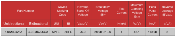
4. Selection Example
Example data:
- VCC = 24 V (nominal operating voltage); maximum operating voltage Vmax = 26 V;
- Downstream circuit can tolerate a maximum transient of 50 V;
- Test waveform: 8/20 μs, test voltage = 500 V;
- Test source internal resistance plus PTC static resistance = 2 Ω.
Steps:
- Choose TVS Vrwm;
- Choose TVS clamping voltage VC;
- Compute actual test waveform power.
Example calculation:
Pactual = Vc * (500 / 3) * 1/2 = 4166 W
Based on the calculation, a 5.0SMDJ26A TVS is suitable; since this TVS is used on a power port, its junction capacitance and leakage are negligible for this application.