 ALLPCB


Introduction
In modern electronics, printed circuit boards face increasing thermal demands from high-power components, lead-free soldering processes, and compact designs. High Tg PCB materials emerge as a critical solution to maintain reliability under elevated temperatures. These materials exhibit a higher glass transition temperature, allowing boards to resist deformation and delamination during manufacturing and operation. Electric engineers must understand high Tg PCB material properties to optimize designs for automotive, aerospace, and telecommunications applications. This guide explores definitions, advantages, and selection criteria to unlock superior performance. By selecting the appropriate material, engineers can mitigate risks associated with thermal stress and ensure long-term board integrity.
What Is Tg in PCB Materials and Why It Matters
The glass transition temperature, denoted as Tg, represents the point where the polymer resin in a PCB laminate shifts from a rigid, glassy state to a softer, rubbery state. Below Tg, the material maintains mechanical strength and dimensional stability, while above it, properties degrade significantly. High Tg PCB materials are defined by specifications like those in IPC-4101, where variants such as /24 or /26 designate elevated Tg thresholds for demanding environments. This property directly influences board performance during reflow soldering, where peak temperatures often exceed standard material limits. For electric engineers, ignoring Tg can lead to warpage, via failures, or interlayer separation in multilayer stacks. Prioritizing high Tg ensures compliance with performance classes outlined in IPC-6012, enhancing overall system reliability.
Key High Tg PCB Material Properties
High Tg PCB material properties center on thermal, mechanical, and electrical characteristics that outperform standard laminates. Thermal stability improves, with reduced coefficient of thermal expansion (CTE) mismatch between layers, minimizing stress during temperature excursions. Mechanical strength persists at higher temperatures, resisting peel strength loss and improving Z-axis expansion control. Electrical properties, such as dielectric constant and dissipation factor, remain consistent under heat, supporting signal integrity in high-frequency designs. These attributes make high Tg materials suitable for environments with prolonged exposure to heat sources like power converters or LEDs. Engineers evaluate these via standardized tests to predict behavior in real-world conditions.
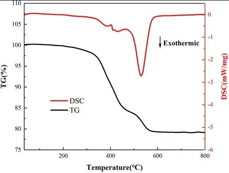
The measurement of Tg follows IPC-TM-650 method 2.4.25, using differential scanning calorimetry (DSC) to detect the transition accurately. This test also assesses cure factor by comparing initial and post-cure scans, ensuring material readiness for fabrication. High Tg variants exhibit sharper transitions and higher onset points, correlating with better process windows. Combined with TMA for Z-axis expansion per IPC-TM-650 2.4.24, these properties guide material qualification. Understanding these metrics allows precise modeling of thermal behavior in simulations.
High Tg FR4: The Workhorse for Elevated Temperatures
High Tg FR4 represents an evolution of the standard FR4 laminate, formulated with modified epoxy resins and fillers to achieve superior heat resistance while retaining cost-effectiveness. Classified under IPC-4101 slash sheets like /126, it supports lead-free assembly profiles without compromising integrity. The material balances flame retardancy, copper peel strength, and insulation resistance, making it ideal for medium to high-volume production. In multilayer boards, high Tg FR4 reduces camber and twist, facilitating automated assembly. Electric engineers favor it for its compatibility with existing processes, requiring minimal adjustments to drill or plate parameters. Its widespread adoption stems from proven performance in Class 3 assemblies per IPC-6012.
Compared to standard FR4, high Tg versions offer extended Td (decomposition temperature), further safeguarding against charring in overheat scenarios. This property proves vital in rework or repair cycles common in prototyping. Fabrication yields improve due to stable resin flow during lamination, ensuring uniform prepreg bonding. Engineers specify high Tg FR4 when designs incorporate dense BGA packages or high-current traces generating localized heat.
High Tg PCB Advantages in Demanding Applications
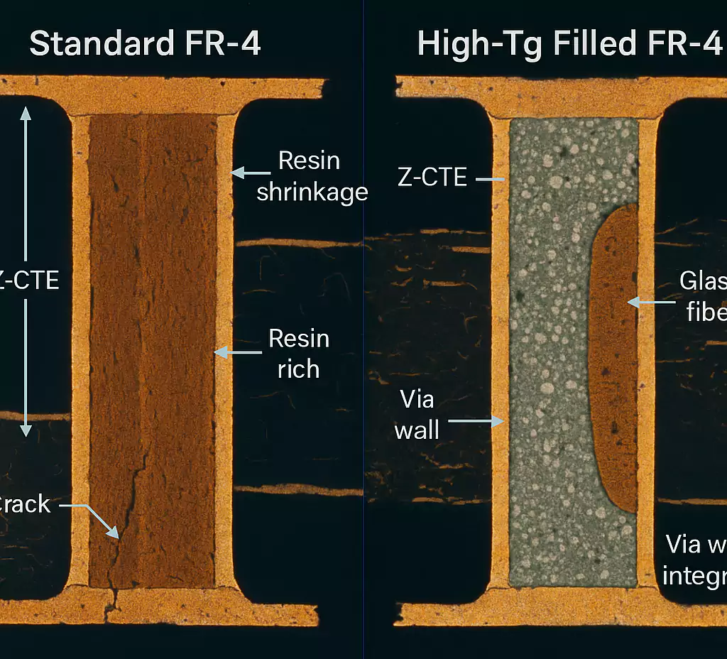
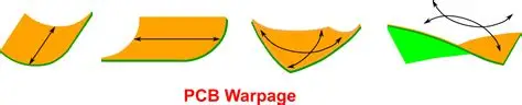
High Tg PCB advantages include enhanced dimensional stability, reducing warpage after reflow or baking, which is critical for fine-pitch components. Boards withstand multiple thermal cycles without microcracks, extending field life in automotive ECUs or industrial controls. Mechanical robustness increases, with higher modulus above Tg, preventing barrel cracking in vias under vibration. Chemical resistance improves against solvents used in cleaning, maintaining surface integrity post-assembly. These benefits translate to higher assembly yields and fewer field failures, optimizing total cost of ownership. For electric engineers, the advantages justify the modest premium in high-reliability sectors.
In power electronics, high Tg materials manage heat from MOSFETs or IGBTs, preventing delamination near hot spots. Signal performance benefits from stable dielectric properties, minimizing crosstalk in RF modules. Compliance with JEDEC J-STD-020 for moisture sensitivity supports storage and handling without degradation. Overall, these advantages enable denser, faster designs without reliability trade-offs.
Choosing the Right Tg Value for Your Design
Choosing the right Tg value requires assessing peak operating temperature, soldering profile, and layer count. Standard FR4 suffices for low-heat logic boards, but high Tg becomes essential when reflow peaks approach or exceed 260 degrees Celsius. Factor in a safety margin of at least 20-30 degrees above maximum process temperature to account for ramp rates and dwell times. Multilayer designs demand higher Tg to counter cumulative CTE stresses between copper and dielectric. Consult IPC-4101 slash sheets to match specifications like /99 for ultra-high Tg in extreme cases. Electric engineers perform thermal profiling early to validate selection.
Consider environmental factors such as humidity, which exacerbates issues via moisture absorption before reflow. High Tg materials often pair with low CTE for balanced expansion. Simulate via FEA tools incorporating material datasheets for warpage prediction. Prototype testing confirms choices, measuring actual Tg post-lamination. This methodical approach aligns material with design goals.
Best Practices for Implementing High Tg PCBs
Specify high Tg materials explicitly in fabrication drawings, referencing IPC-4101 grades to avoid substitutions. Bake boards pre-reflow per JEDEC guidelines to desorb moisture, preventing popcorning. Optimize lamination cycles with slower ramps to ensure full cure without voids. Inspect for warpage using shadow moire per IPC-TM-650 2.4.1, targeting under 0.75% for Class 3. Pair with controlled impedance stackups to leverage stable Dk. These practices maximize high Tg benefits.
During design review, cross-check component datasheets for thermal limits aligning with board Tg. Employ via-in-pad or blind vias judiciously, as high Tg aids plating integrity. Post-assembly, conduct thermal cycling per IPC-6012 to qualify assemblies. Document material certificates verifying Tg compliance. Such diligence ensures robust outcomes.
Conclusion
High Tg PCB materials unlock performance by delivering thermal stability, mechanical strength, and process reliability essential for advanced electronics. Understanding high Tg PCB material properties, high Tg FR4 characteristics, and selection criteria empowers electric engineers to design durable boards. The advantages in warpage control and high-temperature endurance outweigh costs in critical applications. Adhering to standards like IPC-TM-650 and IPC-4101 guarantees quality. Integrate these insights to elevate your projects, ensuring they thrive under thermal stress.
FAQs
Q1: What are the main high Tg PCB material properties electric engineers should prioritize?
A1: High Tg PCB material properties include elevated glass transition temperature for thermal stability, low Z-axis CTE to reduce warpage, and sustained mechanical strength during heat exposure. These ensure reliability in reflow and operation. Per IPC-TM-650 testing, focus on cure factor alongside Tg. Electrical consistency supports high-speed signals. Selecting based on these prevents common failures like delamination.
Q2: What distinguishes high Tg FR4 from standard FR4?
A2: High Tg FR4 features a higher glass transition temperature, typically per IPC-4101 /26, enabling endurance in lead-free processes. It exhibits less expansion and better peel strength at elevated temperatures. Standard FR4 suits benign conditions, while high Tg FR4 excels in multilayers. Advantages include improved assembly yields. Engineers choose it for demanding thermal profiles.
Q3: What are the key high Tg PCB advantages in manufacturing?
A3: High Tg PCB advantages encompass minimal warpage post-reflow, compatibility with multiple cycles, and chemical resistance. These reduce defects in high-volume production. Boards maintain flatness for pick-and-place accuracy. Per IPC-6012, they meet Class 3 criteria reliably. Cost savings arise from fewer rejects.
Q4: How do you go about choosing the right Tg value for a project?
A4: Choosing the right Tg value involves matching peak process temperature with a safety margin, considering layer count and environment. Reference IPC-4101 for grades like high Tg FR4. Simulate thermal stress and prototype test. Higher values suit automotive or power apps. Balance with CTE for optimal performance.
References
IPC-TM-650 2.4.25 — Glass Transition Temperature and Cure Factor by DSC. IPC
IPC-4101 — Specification for Base Materials for Rigid and Multilayer Printed Boards. IPC
IPC-6012E — Qualification and Performance Specification for Rigid Printed Boards. IPC
JEDEC J-STD-020E — Moisture/Reflow Sensitivity Classification. JEDEC


