ALLPCB


If you're facing challenges with Liquid Photoimageable (LPI) solder mask application, such as delamination, pinholes, uneven coating, bridging, or the need for repairs, you're not alone. These issues can disrupt PCB production and affect the quality of the final product. In this comprehensive guide, we’ll walk you through the root causes of these common problems and provide practical solutions to troubleshoot and prevent them. Whether you're an experienced engineer or new to PCB manufacturing, this post will help you achieve a flawless LPI solder mask application.
What is Liquid Photoimageable Solder Mask (LPI)?
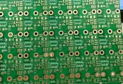
Liquid Photoimageable Solder Mask, commonly known as LPI solder mask, is a protective layer applied to printed circuit boards (PCBs) to insulate copper traces and prevent solder from bridging during assembly. Unlike other types of solder masks, LPI is applied as a liquid and then cured using UV light through a photoimaging process. This method allows for high precision and fine-line resolution, making it ideal for modern, high-density PCB designs.
However, the application process can encounter several issues if not handled with care. Let’s dive into the most common problems associated with LPI solder mask and how to address them effectively.
Common Issues with LPI Solder Mask Application
While LPI solder mask offers numerous benefits, improper application or environmental factors can lead to defects. Below, we’ll explore five frequent issues—LPI solder mask delamination, solder mask pinholes, uneven solder mask coating, solder mask bridging, and solder mask repair—along with actionable troubleshooting steps.
1. LPI Solder Mask Delamination
Delamination occurs when the LPI solder mask peels away from the PCB surface, exposing the underlying copper traces. This issue can compromise the board’s protection and lead to short circuits or corrosion over time.
Causes of LPI Solder Mask Delamination:
- Poor Surface Preparation: Residues like dust, oil, or oxidation on the PCB surface can prevent proper adhesion of the solder mask.
- Inadequate Curing: If the UV curing process is incomplete or the exposure time is insufficient, the solder mask may not bond properly to the board.
- Thermal Stress: Extreme temperature changes during soldering or operation can cause the mask to separate from the substrate.
- Material Incompatibility: Using a solder mask material that is not suited for the PCB substrate can result in poor adhesion.
Solutions for LPI Solder Mask Delamination:
- Thorough Cleaning: Before applying the solder mask, ensure the PCB surface is free of contaminants. Use a chemical cleaner or micro-etching process to remove oxides and improve adhesion.
- Optimize Curing Parameters: Follow the manufacturer’s guidelines for UV exposure time and intensity. Typically, a curing energy of 150-200 mJ/cm2 is recommended for most LPI materials, though this may vary based on the specific formulation.
- Control Thermal Exposure: Minimize thermal shock by preheating the PCB before soldering and using gradual cooling after reflow processes.
- Material Selection: Choose an LPI solder mask compatible with your PCB substrate, such as FR-4 or high-Tg materials, to ensure proper bonding.

2. Solder Mask Pinholes
Pinholes are tiny voids or holes in the solder mask layer that can expose the copper beneath, leading to potential shorts or corrosion. These defects are often hard to detect without magnification but can cause significant issues during assembly or operation.
Causes of Solder Mask Pinholes:
- Air Bubbles: Trapped air during the application process can create voids in the mask as it cures.
- Contamination: Dust or debris on the PCB surface can prevent the mask from coating evenly, resulting in small gaps.
- Improper Viscosity: If the LPI material is too thick or thin due to incorrect mixing or storage, it may not spread uniformly.
- Inadequate Development: During the photoimaging process, underdevelopment can leave residual mask material or create weak spots prone to pinholes.
Solutions for Solder Mask Pinholes:
- Vacuum Application: Use a vacuum chamber during application to remove air bubbles from the liquid mask before curing.
- Clean Environment: Maintain a dust-free workspace to minimize contamination. Use cleanroom standards if possible, targeting a particle count below 100,000 per cubic foot (ISO Class 8 or better).
- Check Viscosity: Ensure the LPI material is within the recommended viscosity range, often between 100-300 centipoise, depending on the product specifications.
- Optimize Development Process: Adjust the development time and chemical concentration to fully remove unexposed mask material without over-etching.

3. Uneven Solder Mask Coating
Uneven solder mask coating refers to inconsistent thickness or coverage across the PCB surface. This can result in areas that are too thin (offering insufficient protection) or too thick (causing issues during assembly).
Causes of Uneven Solder Mask Coating:
- Improper Application Method: Uneven spraying, rolling, or screen printing can lead to inconsistent thickness.
- Board Warpage: If the PCB is not perfectly flat, the solder mask may pool in certain areas and be sparse in others.
- Incorrect Drying Time: Rushing or extending the pre-curing drying phase can cause the mask to settle unevenly.
- Equipment Issues: Worn or misaligned application equipment can result in non-uniform coating.
Solutions for Uneven Solder Mask Coating:
- Standardize Application: Use automated equipment with consistent pressure and speed settings for spraying or rolling. Aim for a target thickness of 0.8-1.2 mils (20-30 micrometers) across the board.
- Ensure Board Flatness: Store and handle PCBs carefully to prevent warpage. Use fixtures during application to keep the board level.
- Monitor Drying Conditions: Follow recommended drying times and temperatures, typically 10-15 minutes at 75-80°C, to allow even settling before curing.
- Maintain Equipment: Regularly calibrate and inspect application tools to ensure uniform delivery of the LPI material.
4. Solder Mask Bridging
Solder mask bridging happens when the mask material unintentionally covers areas it shouldn’t, such as pads or vias meant for soldering. This can interfere with component placement and soldering processes.
Causes of Solder Mask Bridging:
- Excess Material: Applying too much LPI material can cause it to flow into unwanted areas before curing.
- Poor Registration: Misalignment during the photoimaging process can result in the mask covering areas outside the intended design.
- Low Resolution: If the photomask or imaging equipment lacks precision, fine features may not be defined clearly, leading to bridging.
- Inadequate Development: Incomplete removal of unexposed mask material during development can leave residue over pads or vias.
Solutions for Solder Mask Bridging:
- Control Material Volume: Apply the LPI mask in thin, controlled layers to prevent excess flow. Adjust the application settings to achieve a uniform layer without overflow.
- Improve Registration Accuracy: Use high-precision alignment tools to ensure the photomask matches the PCB design perfectly, targeting a tolerance of ±0.002 inches (50 micrometers).
- Enhance Imaging Resolution: Utilize high-resolution imaging systems capable of defining features down to 2 mils (50 micrometers) for intricate designs.
- Refine Development Process: Optimize the development time and chemical strength to fully clear unexposed areas without affecting the cured mask.

5. Solder Mask Repair
Even with the best practices, defects in the solder mask can occur. When issues like delamination, pinholes, or bridging are detected after application, repair becomes necessary to salvage the PCB and avoid costly rework.
Common Challenges in Solder Mask Repair:
- Matching Material: Finding a repair material that matches the original LPI mask in terms of color, adhesion, and thermal properties can be difficult.
- Precision Application: Applying repair material to small, specific areas without affecting surrounding regions requires skill and the right tools.
- Durability: Repaired areas may not withstand the same thermal or mechanical stress as the original mask.
Solutions for Solder Mask Repair:
- Use Compatible Repair Kits: Select a repair material designed for LPI solder masks, ideally from the same supplier as the original mask, to ensure compatibility.
- Manual Application Tools: Use fine-tip brushes or dispensing needles for precise application of repair material to small defects like pinholes or delaminated spots.
- Test Repaired Areas: After curing the repair material (typically at 120-150°C for 30-60 minutes), subject the PCB to thermal cycling tests (e.g., -40°C to 125°C for 100 cycles) to verify durability.
- Document Repairs: Keep detailed records of repair locations and methods to track potential weaknesses in future testing or assembly stages.

Preventive Measures for LPI Solder Mask Application
While troubleshooting is essential, preventing issues in the first place is even better. Here are some proactive steps to ensure a smooth LPI solder mask application process:
- Training and Skill Development: Ensure that operators are well-trained in handling LPI materials and equipment, focusing on proper application and curing techniques.
- Quality Control Checks: Implement regular inspections using automated optical inspection (AOI) systems to detect defects like pinholes or bridging early in the process.
- Environmental Control: Maintain stable temperature and humidity levels in the production area, ideally 20-25°C and 40-60% relative humidity, to prevent material degradation or application inconsistencies.
- Supplier Collaboration: Work closely with your material suppliers to understand the specific requirements and limitations of the LPI solder mask products you use.
Conclusion
Applying Liquid Photoimageable Solder Mask is a critical step in PCB manufacturing, but it comes with challenges like LPI solder mask delamination, solder mask pinholes, uneven solder mask coating, solder mask bridging, and the need for solder mask repair. By understanding the root causes of these issues and implementing the troubleshooting solutions provided in this guide, you can achieve a high-quality solder mask layer that protects your PCBs and ensures reliable performance.
At ALLPCB, we’re committed to supporting engineers and manufacturers with resources and expertise to overcome production challenges. By following best practices and maintaining strict quality control, you can minimize defects and streamline your PCB production process. With the right approach, your LPI solder mask application can be both precise and durable, paving the way for successful electronic assemblies.