 ALLPCB


Introduction
Rigid-flex PCBs combine the benefits of rigid and flexible substrates, enabling compact designs in applications like wearables, medical devices, and aerospace systems. These boards integrate rigid sections for component density with flexible tails or zones for dynamic bending. However, the flex areas often face mechanical challenges during assembly and operation, leading to potential failures such as trace cracking or solder joint fatigue. Rigid-flex PCB stiffeners address these issues by providing targeted mechanical reinforcement. This article explores how stiffeners improve flex PCB reliability, focusing on their role in rigid-flex PCB assembly. Engineers designing high-reliability circuits must understand stiffener selection and integration to optimize performance.
What Are Rigid-Flex PCB Stiffeners and Why Do They Matter?
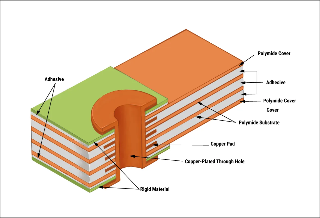
Rigid-flex PCB stiffeners are additional layers of rigid material bonded to specific flex regions, typically polyimide or FR4, to increase local rigidity without altering circuit functionality. They act as flex PCB support structures, preventing excessive bending in vulnerable areas like connector tails or component pads. In rigid-flex designs, stiffeners are essential where flex zones interface with rigid sections or external connectors, mitigating stress concentrations. Without proper stiffeners, flex areas can warp during reflow soldering or handling, compromising rigid-flex PCB assembly yields. Industry standards like IPC-2223 outline design guidelines for these reinforcements, ensuring compliance in multilayer constructions. Ultimately, stiffeners enhance overall board durability, making them critical for applications demanding repeated flexing or high insertion forces.
Stiffeners matter because flex materials, such as polyimide films, inherently lack the mechanical strength of rigid FR4 cores. This flexibility, while advantageous for form factor, exposes circuits to risks like delamination or via barrel cracking under thermal-mechanical stress. In production environments, stiffeners enable automated pick-and-place operations by maintaining planarity, directly impacting throughput and defect rates. For electric engineers, incorporating stiffeners early in design prevents costly rework and field failures. Their use aligns with qualification specs in IPC-6013, which define performance criteria for flexible and rigid-flex boards. By bolstering weak points, stiffeners extend service life in dynamic environments.
Technical Principles Behind Stiffener Performance Enhancement
Stiffeners work by distributing mechanical loads across reinforced areas, reducing strain on copper traces and dielectrics during bending. In flex-to-rigid transitions, they minimize shear forces at material boundaries, preventing microcracks that propagate under cyclic loading. The thickness and modulus of the stiffener material determine its effectiveness; polyimide stiffeners offer thermal compatibility with flex substrates, while FR4 provides higher rigidity for heavy connectors. Bonding methods, such as pressure-sensitive adhesives for general use or thermal lamination for high-reliability, ensure intimate contact and load transfer. This reinforcement improves flex PCB reliability by maintaining consistent bend radii, typically 10 times the substrate thickness, as guided by design standards.
During rigid-flex PCB assembly, stiffeners counteract warpage from solder reflow, where temperature gradients cause flex tails to curl. They provide a stable platform for surface-mount components, reducing tombstoning or bridging defects. In dynamic applications, stiffeners dampen vibrations, protecting solder joints from fatigue. Finite element analysis often reveals that stiffened flex zones exhibit 30% lower principal stresses compared to unreinforced ones, though exact values depend on stackup. Engineers should model stiffener placement to optimize overlap with pads, ensuring uniform support. These principles underscore why stiffeners are integral to achieving robust interconnects in complex assemblies.
The interaction between stiffener and flex layers follows Hooke's law for elastic deformation, where increased flexural stiffness EI (modulus times moment of inertia) resists deflection. Coverlay alignment over traces prevents exposure during stiffening, maintaining electrical isolation. In multilayer rigid-flex, stiffeners on outer flex layers avoid interfering with inner rigid vias. Thermal expansion mismatch is minimized by selecting materials with similar CTEs, such as polyimide (20-30 ppm/°C) matching flex cores. This holistic approach ensures long-term integrity under combined thermal and mechanical cycling.
Best Practices for Rigid-Flex PCB Stiffeners in Design and Manufacturing
Select stiffener materials based on application demands: polyimide for moderate support and heat resistance up to 260°C, FR4 for maximum rigidity in connector areas. Extend stiffener outlines 1-2 mm beyond component footprints to distribute forces evenly, avoiding stress risers at edges. In rigid-flex PCB assembly, position stiffeners opposite SMT components to prevent stencil interference, or use framed stencils for dual-sided application. Thermal bonding outperforms adhesives in class 3 products, providing void-free interfaces per J-STD-001 assembly requirements. Validate designs with bend tests simulating operational cycles, confirming no trace fractures after 10,000 flexes.
Fabrication processes demand precise lamination to avoid air pockets, which could lead to delamination under humidity. Factory insights recommend panelizing flex tails with fiducials for accurate stiffener alignment during automated bonding. For improving flex PCB reliability, incorporate tear stops or anchor points at stiffener edges to contain cracks. Avoid placing vias or fine-pitch traces directly under stiffeners unless blind vias are used. Post-attachment, inspect for adhesion strength via peel tests aligned with IPC standards. These practices yield higher first-pass yields and field performance.
During rigid-flex PCB assembly, stiffeners facilitate wave soldering of through-hole parts by holding flex flat against pallets. Custom fixtures prevent over-bending during conformal coating or potting. For high-volume production, standardize stiffener thicknesses (0.1-0.4 mm) to streamline material handling. Collaborate with fabricators early to confirm coverlay windows align with stiffener perimeters. Troubleshooting common issues like adhesive bleed involves specifying low-flow epoxies and controlled pressure cycles. Consistent adherence to these best practices minimizes variability and enhances overall system reliability.
Troubleshooting Common Stiffener-Related Issues in Rigid-Flex Assemblies
Engineers often encounter warpage in unstiffened flex tails post-reflow, manifesting as lifted pads or open joints. Adding selective stiffeners under BGA footprints resolves this by constraining thermal expansion. Another issue is connector misalignment from repeated matings; thicker FR4 stiffeners (0.2 mm+) provide the necessary rigidity. Delamination at bonds signals adhesive incompatibility, addressed by switching to thermally cured systems for high-temperature profiles. Flex fatigue at stiffener edges requires filleted corners and 0.5 mm overlaps.
In field returns, vibration-induced failures trace to insufficient stiffener coverage; extend supports to cover 80% of dynamic zones. Assembly yields drop if stiffeners interfere with fiducial recognition; offset them slightly from optical marks. Use X-ray inspection for hidden voids under laminates. These factory-driven solutions, rooted in standard qualification flows, prevent recurrence and improve flex PCB reliability.
Conclusion
Rigid-flex PCB stiffeners are vital for bridging the mechanical gap between flexible and rigid domains, ensuring robust performance in demanding applications. By providing targeted flex PCB support, they enhance assembly yields, solder joint integrity, and long-term reliability. Key to success lies in material selection, precise placement, and adherence to standards like IPC-2223 and IPC-6013. Electric engineers should integrate stiffeners proactively in designs to mitigate risks from bending and thermal stresses. Ultimately, these reinforcements enable innovative, compact electronics without sacrificing durability.
FAQs
Q1: What materials are best for rigid-flex PCB stiffeners?
A1: Polyimide offers excellent thermal stability and flexibility matching flex substrates, ideal for most applications. FR4 provides superior rigidity for heavy connectors or high-vibration environments. Select based on operating temperature and mechanical loads, ensuring CTE compatibility to prevent delamination. Factory bonding processes favor these for reliable rigid-flex PCB assembly.
Q2: How do stiffeners improve flex PCB reliability during assembly?
A2: Stiffeners maintain planarity under reflow, preventing warpage that causes solder defects. They support component leads, reducing stress on traces during placement. In rigid-flex designs, they stabilize flex tails for consistent mating. This targeted flex PCB support aligns with J-STD-001, boosting yields and field performance.
Q3: When should engineers add stiffeners to rigid-flex PCBs?
A3: Use stiffeners in connector areas, SMT pads, or flex-rigid junctions prone to bending. They are essential for through-hole components or repeated insertions. Avoid in pure rigid zones unless warpage occurs. Proper placement enhances overall reliability without excess weight.
Q4: What design rules apply to rigid-flex PCB stiffeners?
A4: Extend stiffeners 1-2 mm beyond features for full support, maintaining minimum bend radii. Align with IPC-2223 for multilayer stackups. Bond opposite components to aid stencils. These practices optimize rigid-flex PCB assembly and durability.


