 ALLPCB


If you're looking to enhance the performance of your PCB assembly with surface mount temperature sensors, you've come to the right place. In this guide, we'll dive into the essentials of SMT temperature sensor placement and performance optimization during PCB assembly. We'll cover best practices for positioning, the impact of reflow soldering on sensor accuracy, and techniques for temperature control to ensure reliability. Whether you're an engineer or a hobbyist, you'll find actionable tips to improve your designs using surface mount temperature sensors.
What Are SMT Temperature Sensors and Why Are They Important?
Surface mount temperature sensors, often referred to as SMT temperature sensors, are compact devices designed to measure temperature directly on a printed circuit board (PCB). These sensors are critical in modern electronics for monitoring environmental conditions, ensuring component safety, and maintaining system performance. Unlike traditional through-hole sensors, SMT temperature sensors are soldered directly onto the PCB surface, making them ideal for high-density designs and automated assembly processes.
The importance of an SMT temperature sensor in PCB assembly cannot be overstated. They help prevent overheating, protect sensitive components, and ensure the longevity of devices. For instance, in power electronics, a well-placed sensor can detect temperature spikes and trigger cooling mechanisms to avoid thermal runaway. With applications ranging from consumer gadgets to industrial systems, optimizing SMT sensor performance is a key step in achieving reliable and efficient designs.
Key Factors in SMT Temperature Sensor Placement on PCBs
Placement of an SMT temperature sensor on a PCB is crucial for accurate readings and overall system performance. Poor positioning can lead to incorrect data, delayed thermal responses, or even damage during assembly processes like reflow soldering. Below are the key factors to consider for optimal placement:
1. Proximity to Heat Sources
Place the SMT temperature sensor close to the components or areas that generate the most heat, such as power ICs, MOSFETs, or voltage regulators. For example, if you're designing a power supply board, positioning the sensor near a switching regulator can help monitor temperature rises that could affect performance. However, ensure the sensor isn't so close that it gets damaged by excessive heat—maintain a safe distance of at least 2-3 mm from high-heat components unless specified by the sensor's datasheet.
2. Avoid Airflow Disruptions
Airflow patterns on the PCB can skew temperature readings. Avoid placing sensors in areas with strong airflow from fans or vents, as this can result in lower-than-actual temperature measurements. Instead, position the sensor in a relatively still area of the board for consistent data. If airflow is unavoidable, consider using a small thermal shield around the sensor to stabilize readings.
3. Minimize Electrical Interference
SMT temperature sensors, especially digital ones like I2C or SPI-based models, can be sensitive to electrical noise. Keep them away from high-frequency signal lines or power traces that could introduce interference. For instance, routing a sensor's signal traces perpendicular to high-current paths can reduce noise by up to 30%, based on general PCB layout guidelines.
Impact of Reflow Soldering on SMT Temperature Sensors
Reflow soldering is a critical step in PCB assembly where SMT components, including temperature sensors, are soldered to the board using a controlled heating process. However, the high temperatures involved in reflow soldering can affect the performance and reliability of a reflow soldering temperature sensor if not managed properly. Let’s explore how to mitigate risks during this process.
Understanding the Reflow Soldering Temperature Profile
A typical reflow soldering profile consists of four phases: preheat, soak, reflow, and cooling. During the reflow phase, temperatures can reach up to 245°C for lead-free solder, which may stress sensitive SMT temperature sensors. Most sensors are rated for a maximum soldering temperature (often around 260°C for 10 seconds), so exceeding this limit can degrade accuracy or cause internal damage.
To protect the sensor, ensure the reflow oven’s temperature profile aligns with the sensor manufacturer’s recommendations. For instance, a preheat rate of 1-3°C per second and a peak reflow time above liquidus (around 220°C for lead-free solder) of 30-90 seconds is often ideal for minimizing thermal shock.
Thermal Shock Prevention
Rapid temperature changes during reflow soldering can cause thermal shock, leading to cracks or delamination in the sensor’s package. To avoid this, use a gradual heating approach in the preheat phase (1-2°C per second) and ensure a controlled cooling rate of no more than 4°C per second after reflow. This reduces stress on the sensor’s materials and maintains its long-term reliability.

Optimizing SMT Sensor Performance in PCB Assembly
Optimizing SMT sensor performance goes beyond placement and soldering. It involves design considerations, material selection, and testing to ensure accurate temperature readings and durability. Here are practical tips to achieve the best results:
1. Choose the Right Sensor Type
Not all SMT temperature sensors are created equal. Select a sensor based on your application’s requirements, such as temperature range, accuracy, and response time. For example, thermistor-based sensors offer high accuracy (±0.1°C) for narrow temperature ranges, while digital sensors with I2C interfaces provide flexibility for broader ranges (-40°C to 125°C) with resolutions down to 0.0625°C.
2. Use Proper PCB Materials
The PCB substrate material can influence thermal conductivity and, consequently, sensor performance. FR-4, a common PCB material, has a thermal conductivity of about 0.3 W/m·K, which may not dissipate heat efficiently in high-power applications. For better thermal management, consider high-Tg FR-4 or metal-core PCBs with thermal conductivities up to 2 W/m·K, especially if the SMT temperature sensor monitors critical areas.
3. Implement Calibration and Testing
After assembly, calibrate the SMT temperature sensor to account for any deviations caused by soldering or board layout. Use a controlled temperature chamber to test the sensor at multiple points (e.g., 25°C, 50°C, and 85°C) and compare readings against a reference thermometer. Adjust firmware or apply offset values if discrepancies exceed the sensor’s specified tolerance (typically ±1°C for mid-range sensors).
PCB Assembly Temperature Control Techniques
Effective PCB assembly temperature control is vital for protecting SMT temperature sensors and ensuring the overall quality of the board. Here are some techniques to maintain thermal stability during and after assembly:
1. Use Real-Time Temperature Monitoring
During reflow soldering, employ real-time temperature monitoring tools like thermocouples attached to the PCB. This allows you to track the actual temperature experienced by the SMT temperature sensor and adjust the oven profile if needed. For high-volume production, non-contact infrared cameras can map thermal distribution across multiple boards, ensuring consistency.
2. Incorporate Thermal Relief Pads
Thermal relief pads reduce heat concentration during soldering by limiting the copper connection between the sensor’s pads and large ground planes. This prevents excessive heat from flowing into the sensor, reducing the risk of damage. Design thermal reliefs with spoke widths of 0.2-0.3 mm to balance heat dissipation and electrical connectivity.
3. Post-Assembly Thermal Management
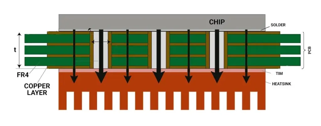
After assembly, integrate heat sinks or thermal vias near high-heat components to manage temperature distribution. For instance, placing thermal vias with a diameter of 0.3 mm and a pitch of 1.2 mm under a power IC can reduce local temperatures by up to 10°C, indirectly benefiting nearby SMT temperature sensors by providing a more stable thermal environment.
Common Challenges and Solutions for SMT Temperature Sensors
Even with careful planning, challenges can arise when working with SMT temperature sensors in PCB assembly. Here are some common issues and how to address them:
1. Inaccurate Readings Due to Board Layout
If the sensor is placed near a large copper pour or ground plane, it may pick up conducted heat rather than ambient temperature. To fix this, isolate the sensor thermally by reducing copper connections around its pads or using a small cutout in the ground plane beneath it.
2. Sensor Damage During Reflow
If a sensor fails post-reflow, it’s often due to exceeding its maximum temperature or time-at-temperature limits. Review the reflow profile and compare it against the sensor’s datasheet. If adjustments aren’t possible, consider hand-soldering the sensor after the main reflow process for sensitive components.
3. Drift Over Time
Long-term exposure to high temperatures can cause sensor drift, where readings become less accurate. To mitigate this, select sensors with low drift specifications (e.g., less than 0.1°C per year) and periodically recalibrate them in critical applications.
Conclusion: Achieving Excellence with SMT Temperature Sensors
Optimizing the placement and performance of SMT temperature sensors in PCB assembly is a multi-faceted process that requires attention to detail at every stage—from design and soldering to testing and thermal management. By carefully positioning your surface mount temperature sensor, adhering to reflow soldering best practices, and implementing robust PCB assembly temperature control techniques, you can ensure accurate readings and reliable operation in your electronic designs.
Whether you're working on consumer electronics, industrial systems, or automotive applications, the tips shared in this guide can help you maximize the effectiveness of your SMT temperature sensor PCB projects. With the right approach, you’ll not only protect your components but also enhance the overall quality and longevity of your assemblies.
Start implementing these strategies in your next project to see the difference in performance and reliability. Remember, a small investment in optimizing SMT sensor performance can yield significant returns in product quality and customer satisfaction.


