 ALLPCB


Introduction
Industrial automation controllers form the backbone of modern robotics, where printed circuit boards (PCBs) integrate processing, sensing, and actuation functions into compact, reliable packages. These boards manage precise movements in robotic arms, handling real-time feedback from encoders and force sensors while driving high-torque motors. PCB design for robotic arm control must address challenges like electromagnetic interference, thermal loads, and mechanical stresses common in factory settings. Embedded systems for industrial robots demand multilayer architectures to separate noisy power domains from sensitive signals. High-reliability PCB manufacturing ensures longevity under continuous operation, minimizing downtime in production lines. This article details the engineering principles, layout strategies, and best practices that enable precision control in these critical applications.
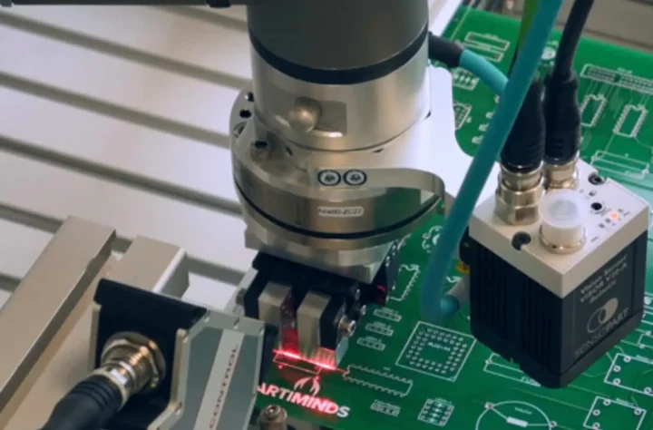
The Role of PCBs in Industrial Automation Controllers
PCBs serve as the central hub in industrial robots, orchestrating communication between microcontrollers, power stages, and peripheral interfaces. They process high-frequency position data and generate pulse-width modulated signals for servo drives, requiring low-latency paths. In harsh environments, boards face vibrations up to 20g and temperatures spanning wide ranges, demanding robust construction. Signal integrity in robotic PCBs prevents errors that could halt operations or cause collisions. High-reliability PCB manufacturing incorporates enhanced inspection and material controls to meet performance specs. Adhering to IPC-2221 guidelines structures the design process from schematic to layout, promoting consistency and manufacturability.
The integration of embedded systems for industrial robots on a single PCB reduces wiring complexity and improves response times. Processors handle motion algorithms, while field-programmable gate arrays accelerate kinematics calculations. Power management ICs regulate supplies for diverse loads, from milliamps for sensors to amps for actuators. Careful partitioning isolates these functions to avoid mutual interference.
Core Technical Principles for PCB Design for Robotic Arm Control
PCB design for robotic arm control prioritizes balanced power delivery and signal fidelity across multiple joints. Each axis requires independent drivers, so layouts group related components to shorten current loops. Microcontrollers sample feedback at kilohertz rates, necessitating clean analog front-ends. Multilayer stackups with dedicated planes control return currents and reduce inductance. Low-Dk materials minimize propagation delays in high-speed links.
Thermal principles guide copper distribution and via placement to spread heat evenly. Motor control circuits generate significant dissipation, so vias connect to inner planes acting as heat spreaders. Mechanical integrity involves anchor points for mounting and strain relief on connectors. These elements ensure the board withstands dynamic loads during arm extensions.

Current handling dictates trace widths, with wider pours for phases carrying peak pulses. Decoupling strategies employ arrays of capacitors tuned to switching frequencies. Ground stitching vias tie planes together, forming low-impedance shields. Simulation tools verify these before fabrication, catching potential hotspots.
Optimized PCB Layout for Motor Control
PCB layout for motor control focuses on minimizing loop areas to suppress radiated emissions. High-side and low-side drivers position near output connectors, routing phases as differential pairs. Gate drive signals demand short, wide traces to preserve sharp edges. Separate analog grounds for current sense shunt feedback avoid contamination from digital noise.
Impedance mismatches cause overshoot in PWM signals, so 50-ohm single-ended or 100-ohm differential routing applies. Via fencing along edges contains fields. IPC-6012 outlines qualification tests for boards enduring such stresses, including thermal cycling and vibration.
Power planes segment by voltage rails, with ferrules or beads filtering ingress. Symmetry in phase routing balances loads across drivers. Test points along critical nets facilitate debugging during integration.
Achieving Signal Integrity in Robotic PCBs
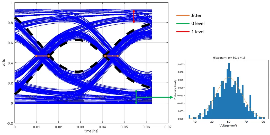
Signal integrity in robotic PCBs safeguards high-speed data from encoders and resolvers against degradation. Crosstalk arises from adjacent traces, mitigated by guard traces or increased spacing. Reflections from impedance steps demand source termination and stub removal. Eye pattern analysis confirms margins for bit error rates below 10^-12.
Length tuning aligns skew in multi-lane buses like those for camera links. Pre-layout planning allocates routing channels adequately. Ground vias near terminations provide clean returns.
Clock distribution uses daisy-chain or star topologies depending on fanout. Serdes channels employ equalization to counter attenuation. Compliance testing verifies emission limits per relevant specs.
High-Reliability PCB Manufacturing Essentials
High-reliability PCB manufacturing starts with material selection for low CTE mismatch, preventing warpage under thermal ramps. Controlled impedance fabrication verifies tolerances within 10 percent. Solder mask dams protect fine-pitch components from bridging. IPC-A-600 criteria define visual acceptability, from plating uniformity to hole walls.
Assembly processes bake boards per JEDEC J-STD-020 to desorb moisture, averting popcorn cracks. Automated X-ray inspects hidden joints for voids. Conformal coatings add barrier protection against dust and humidity.
Traceability logs every step, enabling root-cause analysis. Enhanced cleaning removes flux residues that corrode over time. Functional testing simulates operational stresses.
Best Practices for Implementation
Group components by function in PCB design for robotic arm control, placing hot devices near edges for airflow. Employ blind and buried vias to densify routing without through-hole stubs. DFM reviews flag acute angles prone to etching undercuts. Iterative DRC runs catch violations early.
For embedded systems for industrial robots, modular designs ease upgrades. Redundant power paths enhance availability. Firmware interfaces with hardware diagnostics for self-monitoring.
Vibration testing validates mounting schemes. Documentation includes gerbers with fab notes specifying Class 3A features.
Troubleshooting Common Issues
Noise coupling disrupts encoder reads; isolating grounds resolves it. Voltage droops under load signal inadequate decoupling; larger cap banks fix this. Joint failures from fatigue need underfill or stiffer substrates.
Oscilloscope captures pinpoint sources. Board spins confirm systemic problems.
Conclusion
Precision in industrial automation hinges on thoughtfully designed controller PCBs tailored for robotics demands. From strategic layouts for motor control to rigorous signal integrity measures, each aspect contributes to flawless execution. High-reliability PCB manufacturing upholds these through standards compliance. Engineers applying these principles deliver systems that advance automation reliability and efficiency.
FAQs
Q1: What key factors influence PCB design for robotic arm control?
A1: Prioritize multilayer stackups for domain separation, wide traces for power, and short signal paths for feedback. Vibration mounts and thermal vias ensure durability. Compliance with IPC-2221 structures layouts logically. These practices support synchronized multi-axis motion without latency.
Q2: How does PCB layout for motor control impact performance?
A2: Optimized routing reduces inductance, enabling clean PWM waveforms. Ground planes shield feedback circuits from switching noise. Phase symmetry prevents torque ripple. IPC-6012 testing verifies stability under loads. Proper implementation minimizes EMI and heat buildup.
Q3: Why is signal integrity critical in robotic PCBs?
A3: It preserves timing accuracy for position loops, averting desynchronization. Controlled impedances and shielding curb crosstalk. Length matching suits parallel data. High-reliability manufacturing per IPC-A-600 upholds trace quality. Failures risk safety in dynamic environments.
Q4: What role does high-reliability PCB manufacturing play in embedded systems for industrial robots?
A4: It employs moisture control and inspections for defect-free boards. Coatings resist contaminants. JEDEC guidelines prevent reflow issues. Resulting uptime supports 24/7 operations.
References
IPC-2221B — Generic Standard on Printed Board Design. IPC, 2012
IPC-6012E — Qualification and Performance Specification for Rigid Printed Boards. IPC, 2018
IPC-A-600K — Acceptability of Printed Boards. IPC, 2020
JEDEC J-STD-020E — Moisture/Reflow Sensitivity Classification. JEDEC, 2014





